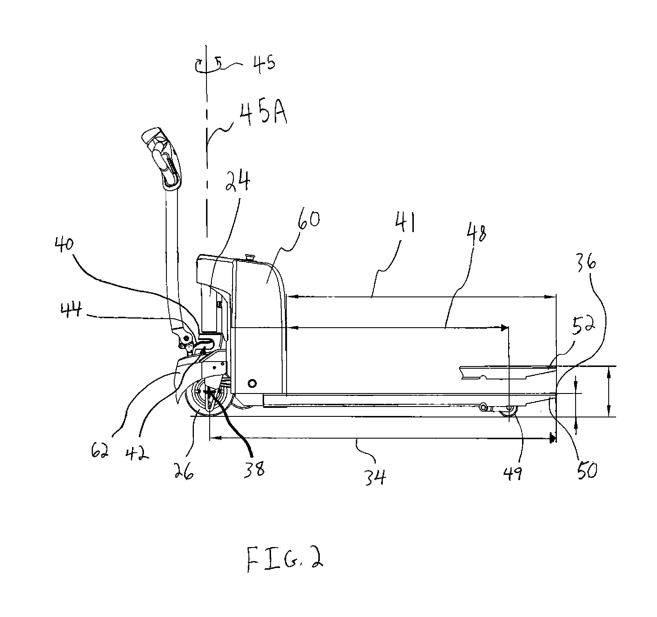
[0009]The pallet truck further includes a pressurized fluid supply mechanism mounted to the load lift portion of the frame assembly forward of the lift mechanism along the central longitudinal axis which is configured to supply pressurized fluid to the lift mechanism through a fluid conduit. In contrast to prior fully-powered pallet trucks having a hydraulic pump mounted on a large stationary rear frame, the pressurized fluid supply mechanism of the subject pallet truck is mounted to the load lift portion of the frame which moves up and down relative to the base support portion of the frame assembly. While this approach runs counter to the approach taken in prior fully-powered pallet trucks, it increases utility of the load lift portion of the frame assembly by using the load lift portion to support the pressurized fluid supply mechanism. In one form, the pressurized fluid supply mechanism, one or more batteries, and a controller of the pallet truck are all mounted to the load lift portion of the frame assembly which provides a compact and lightweight configuration for the fluid supply and electrical systems of the pallet truck. Further, mounting the pressurized fluid supply mechanism to the load lift portion of the frame assembly forward of the lift mechanism provides a powered lift mechanism for the pallet truck without requiring that the base support portion of the frame assembly be sufficiently large to accommodate the pressurized fluid supply mechanism thereon. In this manner, the mounting of the drive motor, the lift mechanism, and the pressurized fluid supply mechanism keeps the overall longitudinal length of the pallet truck to a minimum, such as approximately 54 inches.
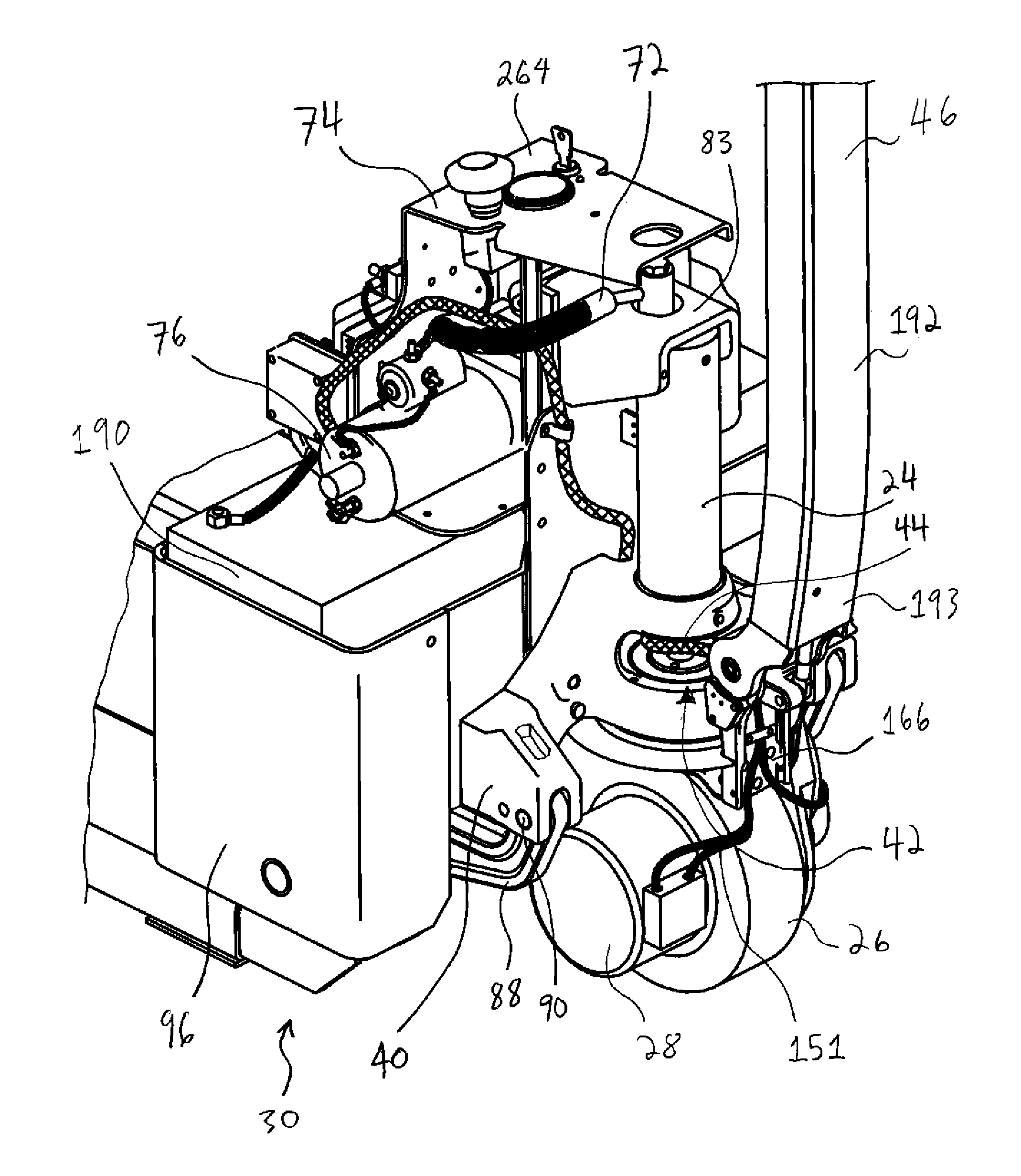
[0010]The load lift portion of the frame may have an upstanding housing portion configured to receive one or more batteries with the fluid supply mechanism mounted to the upstanding housing portion above the one or more batteries. In one form, the fluid supply mechanism includes a hydraulic pump and reservoir both mounted to the upstanding housing portion in a horizontal orientation above the batteries. With the drive motor mounted in the wheel and the one or more batteries are disposed upon a bottom wall of the housing portion, the drive motor, hydraulic pump, reservoir, and one or more batteries are configured to lower the center of gravity of the pallet truck and increase the stability thereof during use.
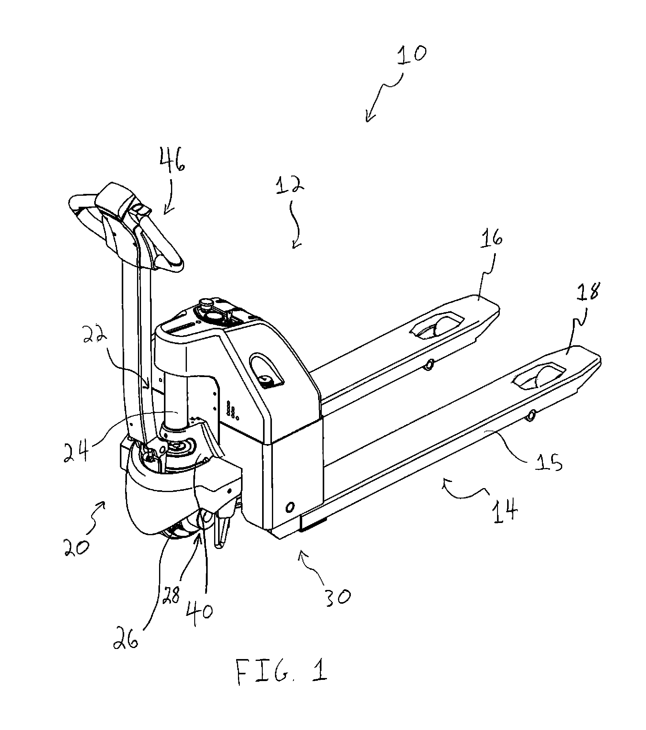
[0011]In a preferred form, the pressurized fluid supply mechanism includes a pump and the frame assembly includes a rearward power head to which the forks are connected and the pump is mounted. The power head has a longitudinal length and the forks have a standard length, with the power head being configured so that the mounting of the drive motor, lift mechanism, and the pump keeps the longitudinal length of the power head to a minimum. In one approach, the power head includes a steering seat to which a steering assembly is mounted, a drive wheel below the steering seat to which the drive motor is mounted, and a pump mount forward longitudinally of the steering mount. The rearward power head further includes a mounting portion to which the lift mechanism is mounted with the connection of the lift mechanism to the power head keeping the longitudinal length of the power head to a minimum. For example, the power head includes a lift mechanism seat to which the lift mechanism is mounted above the steering seat. By minimizing the longitudinal length of the power head, the pallet truck provides easier maneuverability in tight working areas for a given length of the forks.
[0013]The pallet truck further includes a fluid conduit between the lift cylinder device and a pressurized fluid supply mechanism mounted to the load lift portion. The fluid conduit is connected to the upper portion of the lift cylinder device adjacent the pivot connection between the upper portion of the lift cylinder device and the load lift portion of the frame assembly. This configuration limits movement of the fluid conduit during up and down movement of the load lift portion of the frame assembly and the associated pivoting of the upper portion of the lift cylinder device relative to the load lift portion. More specifically, by having separate steering and lift cylinder device seats, the lift cylinder device is not turned each time an operator turns the steering assembly to maneuver the pallet truck which keeps the lift cylinder from turning relative to the fluid conduit and imparting stresses thereto. Further, connecting the fluid conduit to the upper portion of the cylinder adjacent the pivot connection minimizes the change in vertical position of the fluid conduit as the load lift portion moves up and down. Still further, by fixing the lower end portion of the lift cylinder device against longitudinal movement relative to the lift cylinder device seat, horizontal movement of the lift cylinder relative to the pressurized fluid supply device mounted on the load lift portion is minimized during up and down movement of the load lift portion. In this manner, the stresses imparted to the fluid conduit and the connections between the fluid conduit and the lift cylinder and pressurized fluid supply device are reduced and prolongs the lifecycle of the lift cylinder device, fluid conduit, and pressurized fluid supply mechanism.
[0014]In one form, the upper end portion of the lift cylinder device includes a housing having a closed upper end and a lower end opening and the lower end portion of the lift cylinder device includes a piston which reciprocates into and out of the lower end opening of the housing during operation of the lift cylinder device. By utilizing a housing having a closed upper end, the fluid conduit can be connected to the closed upper end which minimizes the distance the fluid conduit needs to extend along the lift cylinder device to supply fluid to the lift cylinder device. As is apparent, the orientation of the lift cylinder device is inverted compared to the hydraulic cylinders of prior fully-powered pallet trucks and provides a powered lift mechanism without having the base support portion be sufficiently large to accommodate the housing and the fluid conduit connected thereto.
[0015]In another aspect of the present invention, a powered pallet truck is provided that includes a frame assembly having a base support portion and a load lift portion with a pair of forks. The pallet truck has a steering assembly rotatably coupled to the base support portion, a control head of the steering assembly for receiving manual inputs from an operator, and one or more cables operably connecting the control head to a controller mounted to the load lift portion of the frame assembly. The base support portion includes an arcuate window sized and configured to receive the one or more cables extending therethrough with the arcuate window permitting movement of the one or more cables within the window as the steering assembly is turned relative to the base support portion. The arcuate window permits the one or more cables to move with turning of the steering assembly without flexing or pinching of the one or more cables due to engagement with the base support portion. Further, the arcuate window provides a range of motion for the one or more cables for the full range of turning of the steering assembly, e.g., 180 degrees, without bending or wrapping the one or more cables around surfaces of the base support portion of the frame assembly.

