Ophthalmic lens element

a technology of ophthalmology and lens elements, applied in the field of ophthalmology lens elements, can solve the problems of hyperopic foveal blur, eye cannot properly focus near objects on the retina, and the eye cannot properly focus distant objects on the retina

Active Publication Date: 2013-09-24
THE VISION CRC LTD
View PDF14 Cites 31 Cited by
  • Summary
  • Abstract
  • Description
  • Claims
  • Application Information

AI Technical Summary

Benefits of technology

[0011]The present invention provides an ophthalmic lens element that provides a distribution of power and surface astigmatism which provides clear foveal vision in a central region and a peripheral region of positive (or “plus”) power relative to the central region. The peripheral region includes dual progressive zones which are located bilaterally of a vertical meridian of the lens element and extend radially outwardly from the central region. The lens element provides a distribution of surface astigmatism which provides a relatively low surface astigmatism on the horizontal meridian of the lens element in both the central region and the progressive zones.
[0012]The distribution of relative plus power throughout the peripheral region provides an optical correction for retarding or arresting myopia for a wearer. Preferably, the lens element provides a distribution of relative plus power that provides a peripheral correction, or “stop signal”, for a region of the periphery of the wearer's retina that lies along a horizontal meridian of the eye. Such a lens element is likely to be effective in correcting hyperopic shifts that occur in the vicinity of the horizontal meridian of the wearer's eye, and thus in retarding or arresting myopia that may result from such a shift.
[0013]The relatively low surface astigmatism on the horizontal meridian of the lens element preferably reduces the magnification of peripheral astigmatism occurring in the wearer's eye along the horizontal meridian of the eye.

Problems solved by technology

If an eyeball is “too long” relative to its “on-axis” focal length (meaning, the focal length along the optical axis of the eye), or if the outside surface (that is, the cornea) of the eye is too curved, the eye will be unable to properly focus distant objects on the retina.
Similarly, an eyeball that is “too short” relative to its on-axis focal length, or that has an outside surface which is too flat, will be unable to properly focus near objects on the retina.
Prolonged reading has been suspected of causing a hyperopic foveal blur due to insufficient accommodation.
The therapeutic benefit of these lenses in clinical trials has been shown to be statistically significant in retarding progression of myopia but clinical significance appears to be limited (e.g., Gwiazda et al., 2003, Invest. Ophthalmol. Vis. Sci., Vol. 44, pp.
Unfortunately, conventional myopia correcting lenses haphazardly produce clear or defocused images in the retina's peripheral region.
Thus, existing ophthalmic lenses for correcting myopia may fail to remove stimuli for Myopia progression.

Method used


Image

  • Ophthalmic lens element
  • Ophthalmic lens element
  • Ophthalmic lens element

Examples


example 2

[0165]FIG. 7 illustrates a contour diagram 700 of surface mean power for another example of an ophthalmic lens element 701 according to an embodiment of the present invention. FIG. 8 illustrates a contour diagram 800 of surface astigmatism for the lens element 701.

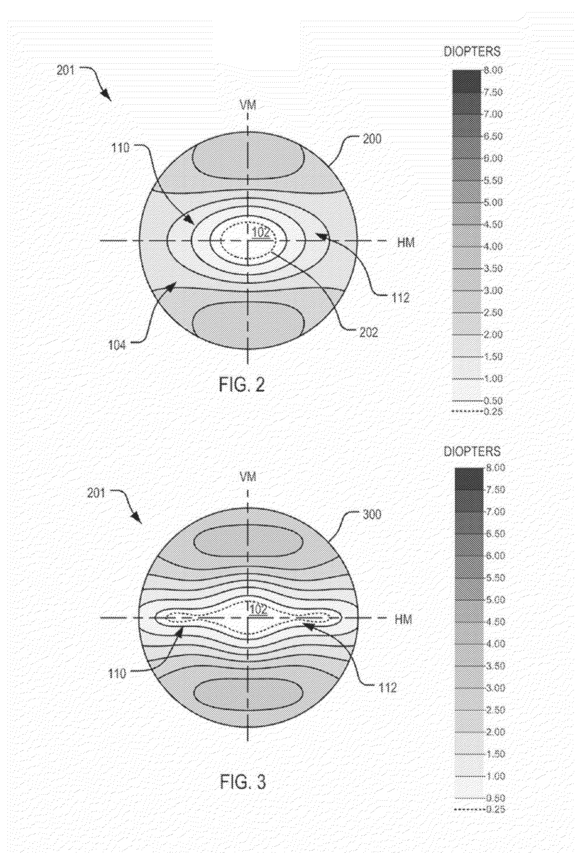
[0166]Lens element 701 is similar to lens element 201 except that lens element 701 provides a larger central region 102 with lower astigmatism (that is, the region bounded by the 0.25 D contour 202 of mean surface power), but provides a distribution of astigmatism which is higher along the horizontal meridian (HM), as is evident in FIG. 8, but is still relatively low on the horizontal meridian (HM) in the central region and the progressive zones.

[0167]In this example, the lens element 701 includes a front surface having the same mean crown curvature as the lens 201 of Example 1, but the mean surface add power reaches 0.25 D only at the radius of 14 mm from the optical centre along the horizontal meridian, compared to 10 mm...

example 3

[0176]FIG. 12 illustrates a contour diagram 1200 of surface mean addition power for another example of an ophthalmic lens element 1201 according to an embodiment of the present invention. FIG. 13 illustrates a contour diagram 1300 of surface astigmatism for the lens element 1201. In this example, the lens element 1201 includes a front surface having a higher mean crown curvature (3.53 D) than the lens element 201 of Example 1.

[0177]Lens element 1201 also provides a central region 102 that has been modified with respect to that of the lens element 201 of Example 1. In particular, the central region 102 of lens element 1201 provides an inset viewing area which is substantially free of astigmatism, but that does not have any addition power. The inset area 1202 is shown in FIG. 12 and is more clearly depicted in FIG. 13.

[0178]The front surface of the lens element 1201 uses the same mathematical description as Example 1, but with the parameter values listed in table 3. However, in this e...

example 4

[0184]FIG. 17 illustrates a contour diagram 1700 of surface mean addition power for another example of an ophthalmic lens element 1701 according to an embodiment of the present invention. FIG. 18 illustrates a contour diagram 1800 of surface astigmatism for the lens element 701.

[0185]As evident from FIG. 17 to FIG. 21, lens element 1701 is similar to lens element 1201 in that it also includes an inset viewing area 1202 which is substantially free of astigmatism, but that does not have any addition power. The inset area 1202 is shown in FIG. 17 and is more clearly depicted in FIG. 18.

[0186]The front surface of the lens element 1701 uses the same mathematical description as Example 1, but with the parameter values listed in table 4.

[0187]

TABLE 4ParameterValueR0136.5mmT0Rl176.67mmM0N0.0000013P3.75A1.0B1.35


PUM


Abstract

An ophthalmic lens element is disclosed. The lens element includes a front surface and a rear surface, at least one which includes a horizontal meridian and a vertical meridian. A central region of the lens element includes a foveal vision zone providing a first power for providing clear foveal vision for a wearer. A peripheral region of positive power relative to the first power is also included. The peripheral region includes dual progressive zones located bilaterally of the vertical meridian and extending radially outwardly from the central region. The lens element provides a distribution of surface astigmatism which provides, on the horizontal meridian, a relatively low surface astigmatism in the central region and the progressive zones.

Description

[0001]This application is a U.S. National Stage Filing under 35 U.S.C. 371 from International Application Number PCT / AU2008 / 001568, filed Oct. 23, 2008 and published in English as WO 2009 / 052570 A1 on Apr. 30, 2009, which claims the benefit of Australian Provisional Patent Application Serial No. 2007905800, filed Oct. 23, 2007; which applications and publication are incorporated herein by reference in their entirety.FIELD OF INVENTION[0002]The present invention relates to ophthalmic lens elements for retarding or arresting myopia, and methods of designing such lens elements.BACKGROUND OF THE INVENTION[0003]To provide focussed vision, an eye must be capable of focusing light on the retina. An eye's ability to focus light on the retina depends, to a large extent, on the shape of the eyeball. If an eyeball is “too long” relative to its “on-axis” focal length (meaning, the focal length along the optical axis of the eye), or if the outside surface (that is, the cornea) of the eye is too ...

Claims


Application Information

Patent Timeline
Patent Type & Authority Patents(United States)
IPC IPC(8): G02C7/06
CPCG02C7/02G02C7/04G02C7/06G02C7/044G02C7/042G02C2202/24G02C7/063
Inventor VARNAS, SAULIUS RAYMOND
Owner THE VISION CRC LTD
Why Eureka
Try Eureka