Necking checking and control method for melted electrode arc welding

A melting electrode and arc welding technology, which is applied in arc welding equipment, welding equipment, manufacturing tools, etc., can solve the problem of unstable control system and achieve the effect of stable control system

Active Publication Date: 2006-10-04
DAIHEN CORP
View PDF2 Cites 15 Cited by
  • Summary
  • Abstract
  • Description
  • Claims
  • Application Information

AI Technical Summary

Problems solved by technology

In order to solve the above problems, if the Figure 8 The above-mentioned magnification Gain, th

Method used


Image

  • Necking checking and control method for melted electrode arc welding
  • Necking checking and control method for melted electrode arc welding
  • Necking checking and control method for melted electrode arc welding

Examples


Embodiment 1

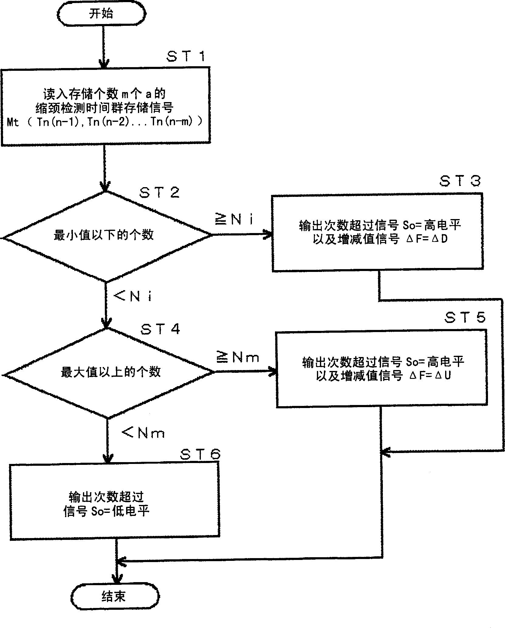
[0039] Embodiment 1 of the present invention is a detection and control method of constriction in molten electrode arc welding, wherein: detecting the constriction detection time in each short circuit, storing a given number m of constriction detection times Tn in the past from the current moment, When the number of stored constriction detection times Tn below the minimum value is greater than or equal to the minimum value, the constriction detection reference value Vtn is reduced by a preset reduction value ΔD, and each stored constriction detection time Tn is not less than the maximum value. When the number of objects is greater than or equal to the maximum value, the constriction detection reference value Vtn is increased by a preset increase value ΔU. Details of Example 1 are described below.

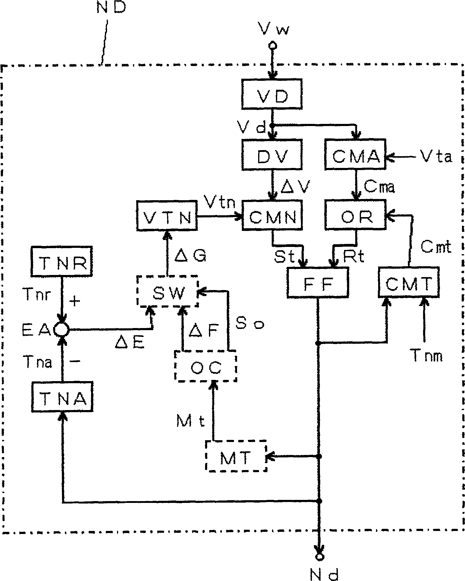
[0040] The block diagram of the welding power source used to implement the detection and control method of the constriction of the molten electrode arc welding in the first embodime...

Embodiment 2

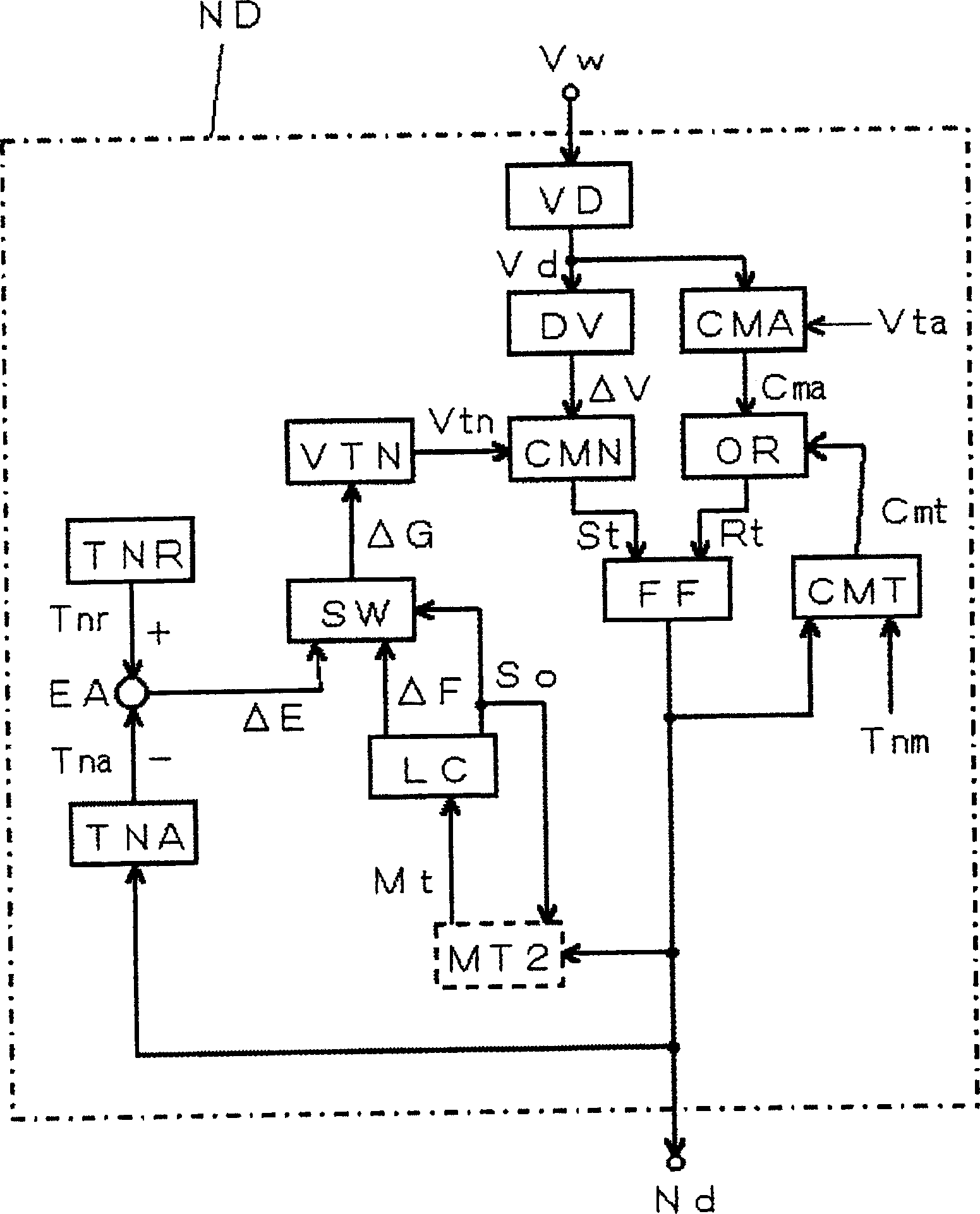
[0047] The block diagram of the welding power source used to implement the detection and control method of the constriction of the molten electrode arc welding according to the second embodiment of the present invention is described in the above-mentioned Figure 5 , so that the necking detection control circuit ND is image 3 The block diagram shown. exist image 3 , for the above figure 1 The same blocks are given the same symbols, and their descriptions are omitted. The following instructions are compatible with figure 1 The different blocks are indicated by dotted lines.

[0048] The second constriction detection time group storage circuit MT2 takes the constriction detection signal nd as an input, detects the constriction detection time of each short circuit, stores constriction detection time groups with a given storage number m in the past from the current moment, and outputs the constriction detection time group. The neck detection time group stores the signal M...


PUM


Abstract

The present invention purposes to improve accuracy of detecting constriction in a method for detecting/controlling constriction in consumable electrode arc welding attended with a short circuit. In this method for detecting/controlling constriction in consumable electrode arc welding, the constrictive phenomenon of a droplet as a sign phenomenon of regeneration of arc from a short-circuit state is detected by that a change in a voltage or resistance value between a consumable electrode and a base metal reaches a reference value Vtn for detecting the constriction, thereby a welding current is rapidly reduced. The constriction detecting time is detected for each short-circuit, storing the detecting time from the current point of time retroactively to the prescribed number of time in the past (MT). When the number of each stored constriction detecting time (Mt) below the minimum value inclusive is not less than the minimum number, the reference value Vtn for detecting the constriction is decreased by the variation [Delta]F. When the number of each stored constriction detecting time (Mt) above the maximum value inclusive is not less than the maximum number, the reference value Vtn for detecting the constriction is increased by the variation [Delta]F. Thus, the reference value Vtn for detecting the constriction is optimized.

Description

technical field [0001] The invention relates to a necking detection and control method for molten electrode arc welding which detects the necking phenomenon of molten droplets during short circuit, reduces welding current sharply and improves welding quality. Background technique [0002] Figure 4 It is a graph showing the current, voltage waveform, and droplet transfer in molten electrode arc welding in which the short-circuit period Ts and the arc period Ta are repeated. Figure 4 (A) represents the time change of the welding current Iw energized to the melting electrode (hereinafter referred to as electrode 1), Figure 4 (B) shows the time change of the welding voltage Vw applied between the electrode 1 and the base metal 2, Figure 4 (C) to (E) show the state of transfer of the droplet 1a. Refer below Figure 4 Be explained. [0003] During the short-circuit period Ts from time t1 to t3, the droplet 1a at the top of the electrode 1 is in a short-circuit state with the b...

Claims


Application Information

Patent Timeline
IPC IPC(8): B23K9/06B23K9/10
Inventor 惠良哲生井手章博水取裕康
Owner DAIHEN CORP
Why Eureka
Try Eureka