Check patentability & draft patents in minutes with Patsnap Eureka AI!

Control circuit, power conditioner including the control circuit, and photovoltaic system

a control circuit and power conditioner technology, applied in the direction of dc-ac conversion without reversal, process and machine control, instruments, etc., can solve the problems of adversely affecting the highly accurate operation of the power conditioner, and achieve the effect of accurate operation and high accuracy

Active Publication Date: 2013-09-24
ORMON CORP
View PDF10 Cites 0 Cited by
  • Summary
  • Abstract
  • Description
  • Claims
  • Application Information

AI Technical Summary

Benefits of technology

[0013]A non-limiting feature of the disclosure is to solve the problems described above, and a feature thereof is to provide a power conditioner enabling highly accurate operation by calibrating the in-phase component in the output of the differential amplifier circuit as an in-phase error, and a photovoltaic system equipped with the same.
[0019]According to the present disclosure, since the in-phase error is calibrated from the output of the differential amplifier circuit for differentially amplifying (that differentially amplifies) the inter-end voltage of the capacitor, the switch element can be ON / OFF controlled at higher accuracy in the control circuit that controls the ON / OFF of the switch element by the output of the differential amplifier circuit, and consequently, a more accurate operation can be carried out in the power conditioner equipped with such a control circuit.

Problems solved by technology

However, if an in-phase component (see detailed description in the embodiments) is contained in both input components to the differential amplifier circuit, the in-phase component appears in the output of the differential amplifier circuit as an error component, in which the error component also appears in a digital measurement signal as an A / D conversion value of the differential amplifier circuit output in the control circuit section, thus adversely affecting the highly accurate operation of the power conditioner since the ON / OFF control of the switch element is carried out by the error component.

Method used


Image

  • Control circuit, power conditioner including the control circuit, and photovoltaic system
  • Control circuit, power conditioner including the control circuit, and photovoltaic system
  • Control circuit, power conditioner including the control circuit, and photovoltaic system

Examples


Embodiment Construction

[0053]Hereinafter, preferred embodiments of the present disclosure will be described with reference to the drawings.

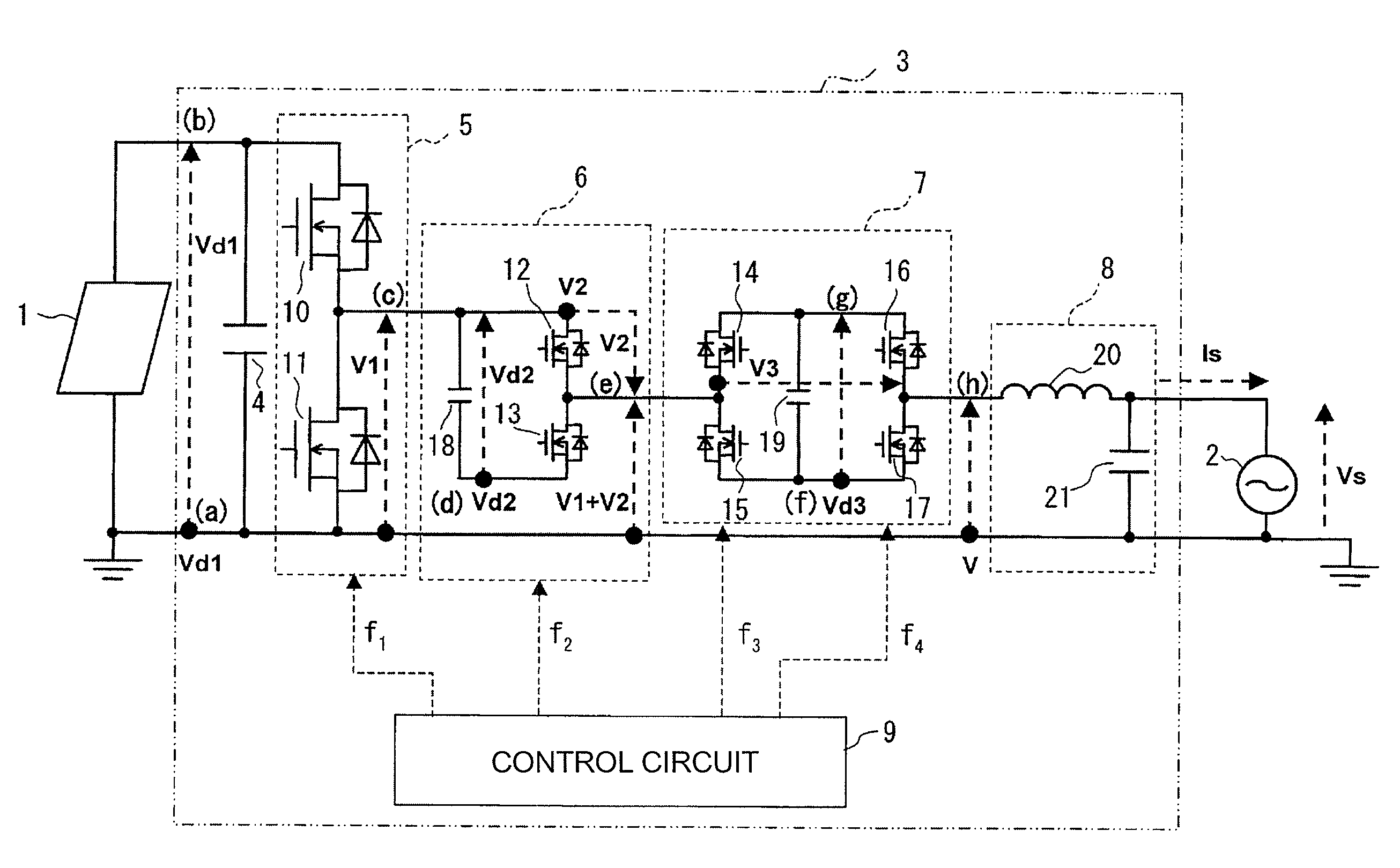
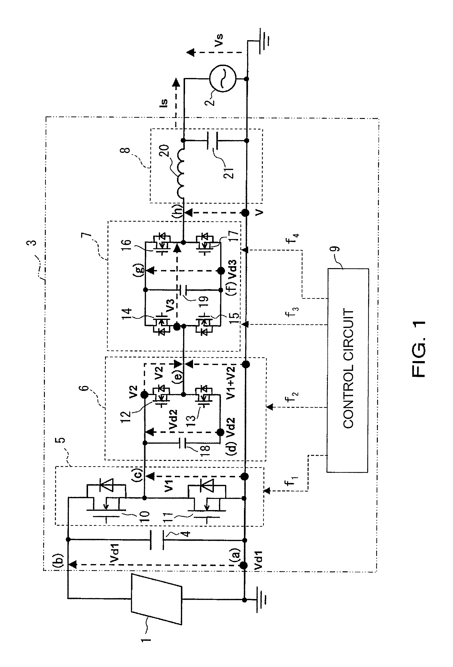
[0054]FIG. 1 is a configuration diagram of a photovoltaic system according to one embodiment of the present disclosure, showing a configuration for a case of single-phase two-wire.

[0055]The photovoltaic system of the embodiment includes a solar cell panel 1, and a power conditioner 3 for converting the DC power from the solar cell panel 1 to the AC power and operating while being interconnected to a commercial power supply 2.

[0056]The solar cell panel 1 is configured by connecting a plurality of solar cell modules in series and in parallel to obtain a desired generated power.

[0057]The solar cell panel 1 of the embodiment is configured by a thin film solar cell made of amorphous silicon.

[0058]The power conditioner 3 of the present embodiment is a non-insulating type (transformer-less) power conditioner not including an insulating transformer.

[0059]The power conditioner ...


PUM


Abstract

A power conditioner of a photovoltaic system is configured operate at higher accuracy. A chopper circuit, a capacitor connected in parallel to the chopper circuit, and a control circuit that controls an ON / OFF status of switch elements in the chopper circuit to control charging and discharging of the capacitor are provided. The control circuit includes a measurement control section that measures an inter-end voltage of the capacitor and a control circuit section that performs a predetermined control operation from a measurement output of the measurement circuit section. The measurement circuit section includes a differential amplifier circuit that differentially amplifies the inter-end voltage of the capacitor. The circuit control section calibrates an in-phase component in the output of the differential amplifier circuit as an in-phase error and performs the control from the calibrated output from the differential amplifier circuit.

Description

CROSS-REFERENCE TO RELATED APPLICATION[0001]This application claims benefit of priority under 35 U.S.C. §119 to Japanese Patent Application No. P2010-054246 filed on Mar. 11, 2010, which is expressly incorporated herein by reference in its entirety.BACKGROUND[0002]1. Field of the Disclosure[0003]The present disclosure relates to a control circuit, a power conditioner including the control circuit, and a photovoltaic system.[0004]2. Background Information[0005]A photovoltaic system generally converts a direct-current (DC) power from a solar cell to an alternating-current (AC) power of a commercial frequency that is interconnected to a system by a power conditioner and also supplies the converted AC power to an in-house load connected to a commercial power system, where excessive power is reversely flowed to the system side if the AC power is greater than the consumption power of the in-house load. In such a power conditioner, a non-insulating type excelling in power conversion effici...

Claims


Application Information

Patent Timeline
Patent Type & Authority Patents(United States)
IPC IPC(8): H02M1/12
CPCH02M7/49H02M7/797H03F3/45475H02M2007/4835H03F2203/45604H03F2203/45528H03F2203/45594Y02E10/56H02M7/4835H02M1/0095H02J3/38H02M7/48H02J7/35G05F1/67
Inventor MABUCHI, MASAOMIYAMOTO, MIOMAKI, NAOKINAKAMURA, KOTAROTSUNAGA, AKIYUKI
Owner ORMON CORP
Features
  • R&D
  • Intellectual Property
  • Life Sciences
  • Materials
  • Tech Scout
  • Unparalleled Data Quality
  • Higher Quality Content
  • 60% Fewer Hallucinations
Learn More