Check patentability & draft patents in minutes with Patsnap Eureka AI!

Robot controlling method, robot apparatus, program and recording medium

a robot and control method technology, applied in the direction of programmed manipulators, programme control, instruments, etc., can solve the problems of several millimeter error of the robot end, and the inability to accurately control the robot. the effect of the robot end

Active Publication Date: 2016-10-13
CANON KK
View PDF5 Cites 12 Cited by
  • Summary
  • Abstract
  • Description
  • Claims
  • Application Information

AI Technical Summary

Benefits of technology

The present invention aims to reduce the amount of calculation and errors in position and orientation of a robot end. The first correction quantity is obtained by using the error component in the driving direction of the actuator of each joint, and the correction error in the first correction quantity is reduced. The residual error excluding the error component in the driving direction of the actuator is smaller than the error component in the driving direction of the actuator, and the second correction quantity obtained from the error in position and orientation of the end point of the robot based on the residual error of each joint is smaller than the first correction quantity. Therefore, the second correction quantity includes the correction error when obtained from the error in position and orientation of the end point of the robot, and the correction error in the second correction quantity is small. As a result, both the first correction quantity and the second correction quantity have small correction errors, and the convergent calculation does not have to be performed, reducing the amount of calculation required. The use of the first correction quantity and the second correction quantity with small correction errors reduces the error in position and orientation of the end point of the robot, leading to highly accurate operation of the robot.

Problems solved by technology

However, there is a difference (trajectory error) between the instruction trajectory of the robot and an actual trajectory of the robot.
The trajectory error is an obstacle in precise work by the robot.
The error in position and orientation of each joint includes an error in a driving direction of the joint as well as errors in other directions.
The error of the robot end is several millimeters due to the effect of the error in position and orientation of each joint.
Therefore, the correction quantity for correcting the joint instruction value of each joint calculated by the inverse mechanism calculation always includes a calculation error.
When the error of the robot end is large, a correction error of the correction quantity that occurs at the correction of the error is also large.
Therefore, the correction quantity of the joint instruction value of each joint cannot be obtained with a sufficient accuracy by one calculation in the conventional technique.
If restrictions of convergence determination are eased to reduce the calculation time required for the convergent calculation, the correction error increases, and highly accurate correction is difficult.

Method used


Image

  • Robot controlling method, robot apparatus, program and recording medium
  • Robot controlling method, robot apparatus, program and recording medium
  • Robot controlling method, robot apparatus, program and recording medium

Examples


first embodiment

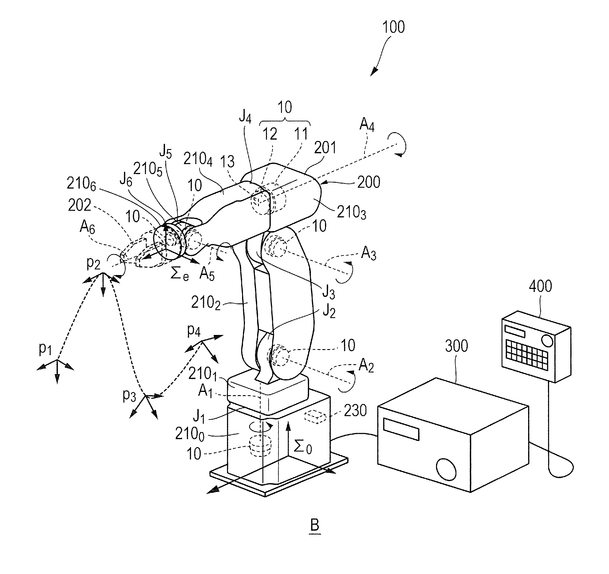
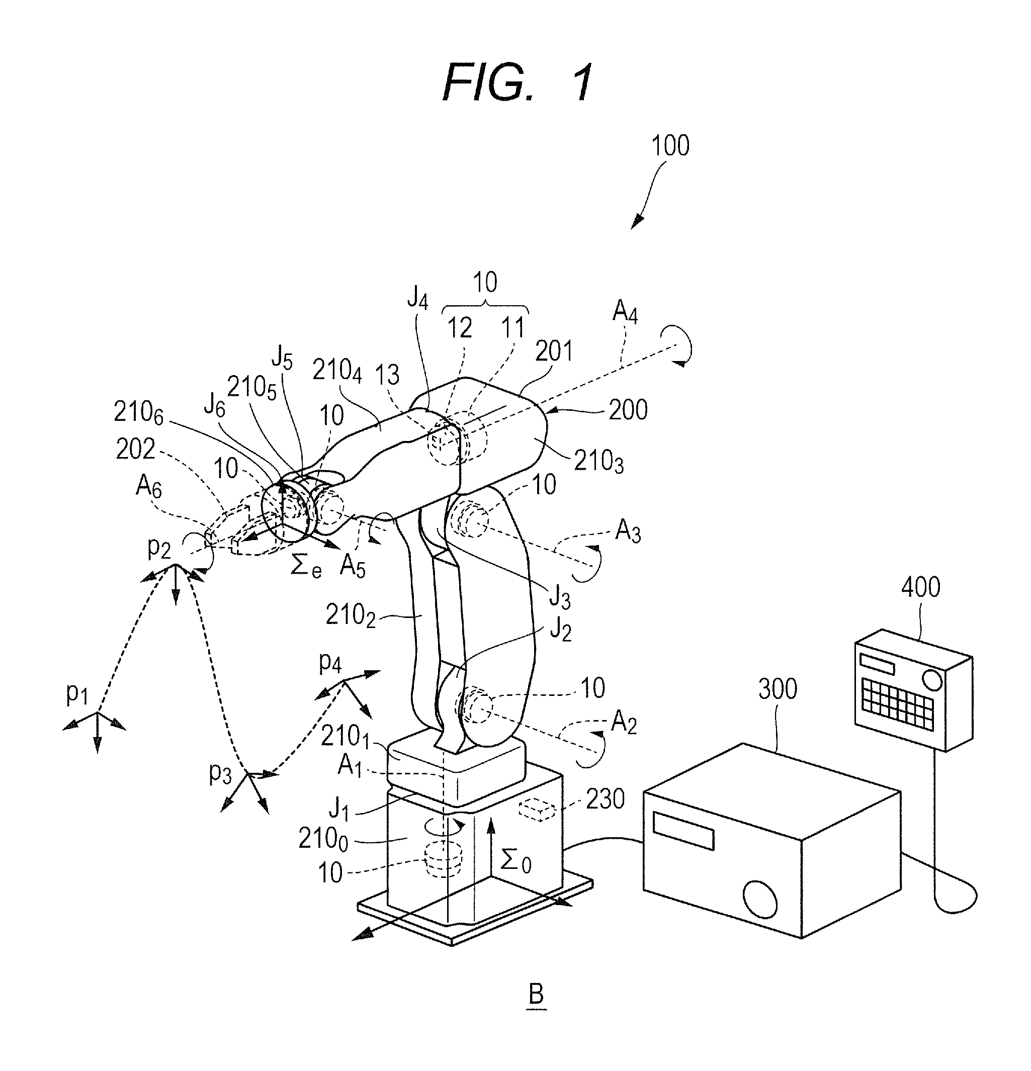
[0062]FIG. 1 is a perspective view illustrating a schematic configuration of a robot apparatus according to a first embodiment of the present invention. As illustrated in FIG. 1, a robot apparatus 100 includes a multi-joint robot 200 and a robot controlling apparatus 300 as a controlling unit that controls operation of the robot 200. The robot apparatus 100 also includes a teaching pendant 400 as a teaching apparatus that transmits data of a plurality of teaching points to the robot controlling apparatus 300. The teaching pendant 400 is operated by a person and is used for designating operation of the robot 200 and the robot controlling apparatus 300.

[0063]The robot 200 is a vertical multi-joint robot. More specifically, the robot 200 includes a vertical multi-joint robot arm 201 and a robot hand 202 as an end effector mounted on an end point of the robot arm 201. Although the end effector is the robot hand 202 in the following description, the end effector is not limited to this, a...

second embodiment

[0182]Next, a robot controlling method in a robot apparatus according to a second embodiment of the present invention will be described. FIG. 9 is a flow chart illustrating the robot controlling method according to the second embodiment of the present invention. A configuration of the robot apparatus according to the second embodiment is the same as the configuration of the robot apparatus illustrated in FIGS. 1 and 2 described in the first embodiment, and the description will not be repeated.

[0183]The flow chart of FIG. 9 illustrates control by the robot controlling apparatus 300, or specifically, the CPU 301, that follows the program 330.

[0184]In the second embodiment, the order of separating the joint driving direction component from the entire errors is different from the first embodiment. The different point will be mainly described here. As described in FIG. 1, the actuators 10 with combinations of the motors 11 and the reduction gears 12 drive the joints J1 to J6 of the robot...

third embodiment

[0194]Next, a robot controlling method in a robot apparatus according to a third embodiment of the present invention will be described. FIG. 10 is a perspective view of a robot of the robot apparatus according to the third embodiment of the present invention. FIG. 11 is a block diagram illustrating a robot controlling apparatus of the robot apparatus according to the third embodiment of the present invention. In the third embodiment, the same components as in the first and second embodiments are designated with the same signs, and the description will not be repeated.

[0195]In the description of the first embodiment, the errors in position and orientation of the fixed end of the joint Ji are provided in advance as fabrication error parameters. The third embodiment is different from the first embodiment in that the fabrication error parameters are corrected based on detection values of a plurality of temperature sensors provided at each position of the robot 200.

[0196]In the robot 200...


PUM


Abstract

A controlling unit obtains an error in position and orientation of each joint of a robot. The controlling unit uses an error component in a driving direction of an actuator included in the error in position and orientation ui of the joint to obtain a first correction quantity, to obtain a residual error excluding the error component in the driving direction of the actuator from the error in position and orientation of the joint, and to obtain—an error in position and orientation of the end point of the robot based on the residual error of each joint. The controlling unit uses the error in position and orientation of the joint based on the error in position and orientation of the end point of the robot to obtain a second correction quantity Δqi, and uses the first correction quantity and the second correction quantity to correct a joint instruction value.

Description

BACKGROUND OF THE INVENTION[0001]1. Field of the Invention[0002]The present invention relates to a robot controlling method, a robot apparatus, a program and a recording medium for controlling operation of each joint of a robot according to each joint instruction value.[0003]2. Description of the Related Art[0004]In recent years, robot apparatuses engaged in production, such as assembly, are developed in many cases. An ultimate object of the robot apparatus is to realize complicated and fast assembly work, like that of a hand of a human, in a robot. The robot is controlled according to an instruction trajectory, that is, a joint instruction value of each joint (joint instruction value indicating an angle in a case of a rotary joint, joint instruction value indicating a length in a case of a linear motion joint). However, there is a difference (trajectory error) between the instruction trajectory of the robot and an actual trajectory of the robot. The trajectory error is an obstacle ...

Claims


Application Information

Patent Timeline
Patent Type & Authority Applications(United States)
IPC IPC(8): B25J9/16
CPCG05B2219/39176B25J9/1638B25J9/1692G05B2219/37431G05B2219/39191G05B2219/39192G05B2219/39206
Inventor NEGISHI, MAHITO
Owner CANON KK
Features
  • R&D
  • Intellectual Property
  • Life Sciences
  • Materials
  • Tech Scout
  • Unparalleled Data Quality
  • Higher Quality Content
  • 60% Fewer Hallucinations
Learn More