Check patentability & draft patents in minutes with Patsnap Eureka AI!

Three-dimensional measuring device

a three-dimensional measuring and measuring device technology, applied in the direction of electrical programme control, program control, instruments, etc., can solve the problems of inability to negligible the measurement error produced by such minute variations in the position of the robot, difficulty in achieving accurate coupling, etc., and achieve the effect of suppressing the adverse effects of backlash

Active Publication Date: 2005-11-29
FANUC LTD
View PDF3 Cites 29 Cited by
  • Summary
  • Abstract
  • Description
  • Claims
  • Application Information

AI Technical Summary

Benefits of technology

[0007]The present invention provides a three-dimensional measuring device capable of reducing adverse effects of the coordinate system coupling error and the robot position error due to backlash, thus permitting a robot to perform a highly accurate operation.
[0011]The control means may control the robot to position the visual sensor at an auxiliary position / orientation before positioning the visual sensor at the preparatory or main measurement position / orientation, said auxiliary position / orientation being determined such that a motion of the visual sensor from the auxiliary position / orientation to the preparatory or main measuring position / orientation is realized by rotating all of drive motors of the robot unidirectionally. In this case, the three-dimensional measuring device is made able to suppress adverse effects of backlash to the measurement accuracy, which effects vary depending on the operating direction of articulated axes of the robot.

Problems solved by technology

In practice, however, an accurate coupling is generally quite difficult to achieve due to various reasons, so that an inevitable coupling error may be caused.
Due this coupling error, a measurement error may be caused in a measurement performed while changing the position / orientation of robot, which error is unnegligible depending on application.
In some applications, a measurement error produced by such minute variation in robot position cannot be negligible.

Method used


Image

  • Three-dimensional measuring device
  • Three-dimensional measuring device
  • Three-dimensional measuring device

Examples


Embodiment Construction

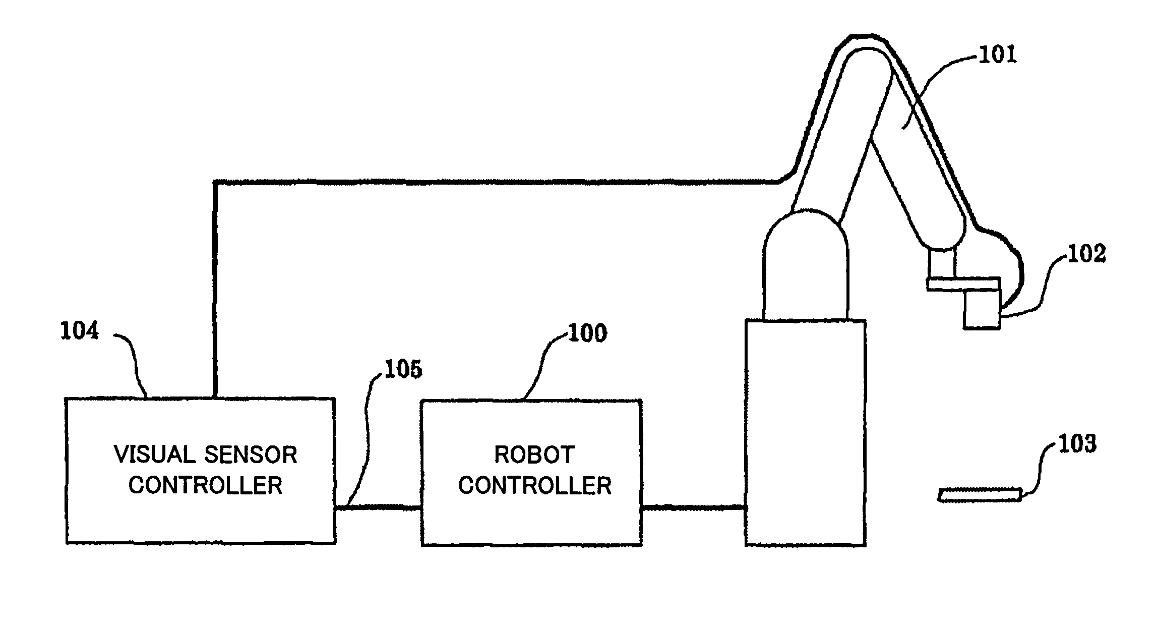
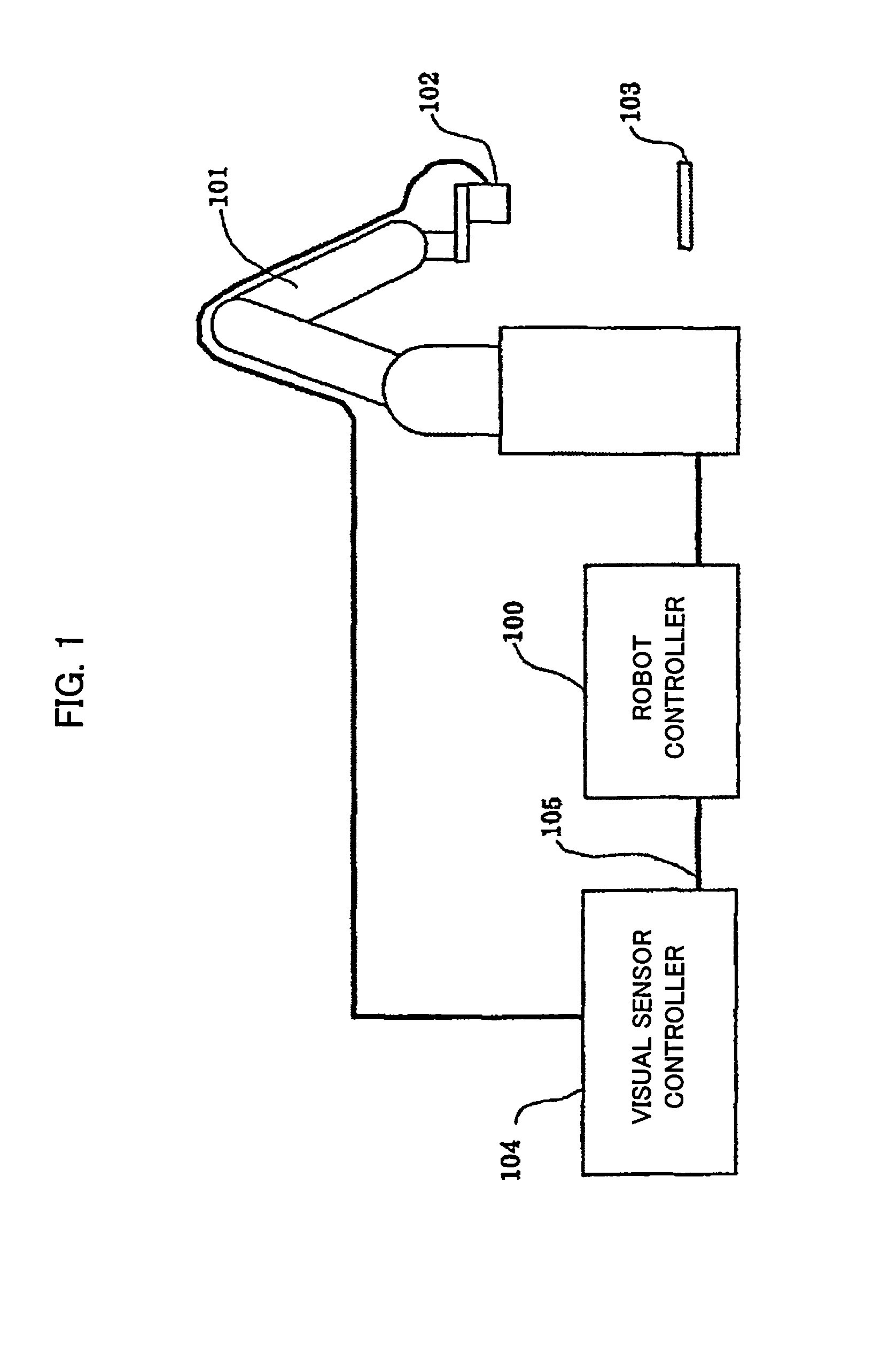
[0020]FIG. 1 is a view for explaining the overall configuration of a three-dimensional measuring device according to an embodiment of this invention. As shown in FIG. 1, the three-dimensional measuring device comprises a three-dimensional visual sensor comprised of a sensor head 102 and a visual sensor controller 104, and a robot 101 connected to a robot controller 100 and having an arm end mounted with the sensor head 102 of the visual sensor. The visual sensor controller 104 is connected with the sensor head 102 and also connected through a communication line 105 with the robot controller 100.

[0021]Reference numeral 103 denotes an object (for instance, a workpiece) whose position / orientation is to be measured by the visual sensor. Although illustration is omitted, a teaching pendant is connected to the robot controller 100 as is well known, through which various commands may manually be input. This manual input includes jog feed in the robot, input of a measurement command for the...


PUM


Abstract

Three-dimensional measurement capable of reducing an error in coupling robot and sensor coordinate systems and adverse effects of backlash in a robot. A position / orientation of the robot for obtaining a measurement value on the sensor coordinate system is set beforehand with a workpiece positioned at a reference position. Then, the robot is moved to a preparatory measurement position, a preparatory measurement for the workpiece positioned at an arbitrary position is performed (SV1), and based on a measurement result, a main measurement position is calculated (SV2). Next, an auxiliary position is determined (SV3), which serves as a start position from which a movement to the main measurement position can be made without making a reversal of respective axes. The robot is moved to the auxiliary position (SV4), and to the main measurement position (SV5), and a measurement for the workpiece is made and a measurement result is stored (SV6).

Description

BACKGROUND OF THE INVENTION[0001]1. Field of the Invention[0002]The present invention relates to a device, having a three-dimensional visual sensor mounted to a robot, for three-dimensional measurement of an object, which device is utilized for an application performing a three-dimensional measurement of a workpiece for instance for workpiece ejection, workpiece machining, etc.[0003]2. Description of Related Art[0004]In a three-dimensional measurement of an object such as a workpiece using a three-dimensional visual sensor mounted to a robot, a sensor coordinate system must be coupled in advance with a robot coordinate system. An exemplified method therefor is disclosed in JP 10-63317A relating to a “method for coupling coordinate systems in a robot and visual sensor system.”[0005]In practice, however, an accurate coupling is generally quite difficult to achieve due to various reasons, so that an inevitable coupling error may be caused. Due this coupling error, a measurement error m...

Claims


Application Information

Patent Timeline
IPC IPC(8): B25J9/16B25J13/08G01B11/00G01B11/03G01B21/04
CPCB25J9/1641B25J9/1697G01B21/045G05B2219/39057
Inventor BAN, KAZUNORIKANNO, ICHIRO
Owner FANUC LTD
Features
  • R&D
  • Intellectual Property
  • Life Sciences
  • Materials
  • Tech Scout
  • Unparalleled Data Quality
  • Higher Quality Content
  • 60% Fewer Hallucinations
Learn More