Check patentability & draft patents in minutes with Patsnap Eureka AI!

Control circuit, power conditioner including the control circuit, and photovoltaic system

Active Publication Date: 2011-09-15
ORMON CORP
View PDF5 Cites 4 Cited by
  • Summary
  • Abstract
  • Description
  • Claims
  • Application Information

AI Technical Summary

Benefits of technology

[0013]A non-limiting feature of the disclosure is to solve the problems described above, and a feature thereof is to provide a power conditioner enabling highly accurate operation by calibrating the in-phase component in the output of the differential amplifier circuit as an in-phase error, and a photovoltaic system equipped with the same.
[0019]According to the present disclosure, since the in-phase error is calibrated from the output of the differential amplifier circuit for differentially amplifying (that differentially amplifies) the inter-end voltage of the capacitor, the switch element can be ON / OFF controlled at higher accuracy in the control circuit that controls the ON / OFF of the switch element by the output of the differential amplifier circuit, and consequently, a more accurate operation can be carried out in the power conditioner equipped with such a control circuit.

Problems solved by technology

However, if an in-phase component (see detailed description in the embodiments) is contained in both input components to the differential amplifier circuit, the in-phase component appears in the output of the differential amplifier circuit as an error component, in which the error component also appears in a digital measurement signal as an A / D conversion value of the differential amplifier circuit output in the control circuit section, thus adversely affecting the highly accurate operation of the power conditioner since the ON / OFF control of the switch element is carried out by the error component.

Method used


Image

  • Control circuit, power conditioner including the control circuit, and photovoltaic system
  • Control circuit, power conditioner including the control circuit, and photovoltaic system
  • Control circuit, power conditioner including the control circuit, and photovoltaic system

Examples


Embodiment Construction

[0053]Hereinafter, preferred embodiments of the present disclosure will be described with reference to the drawings.

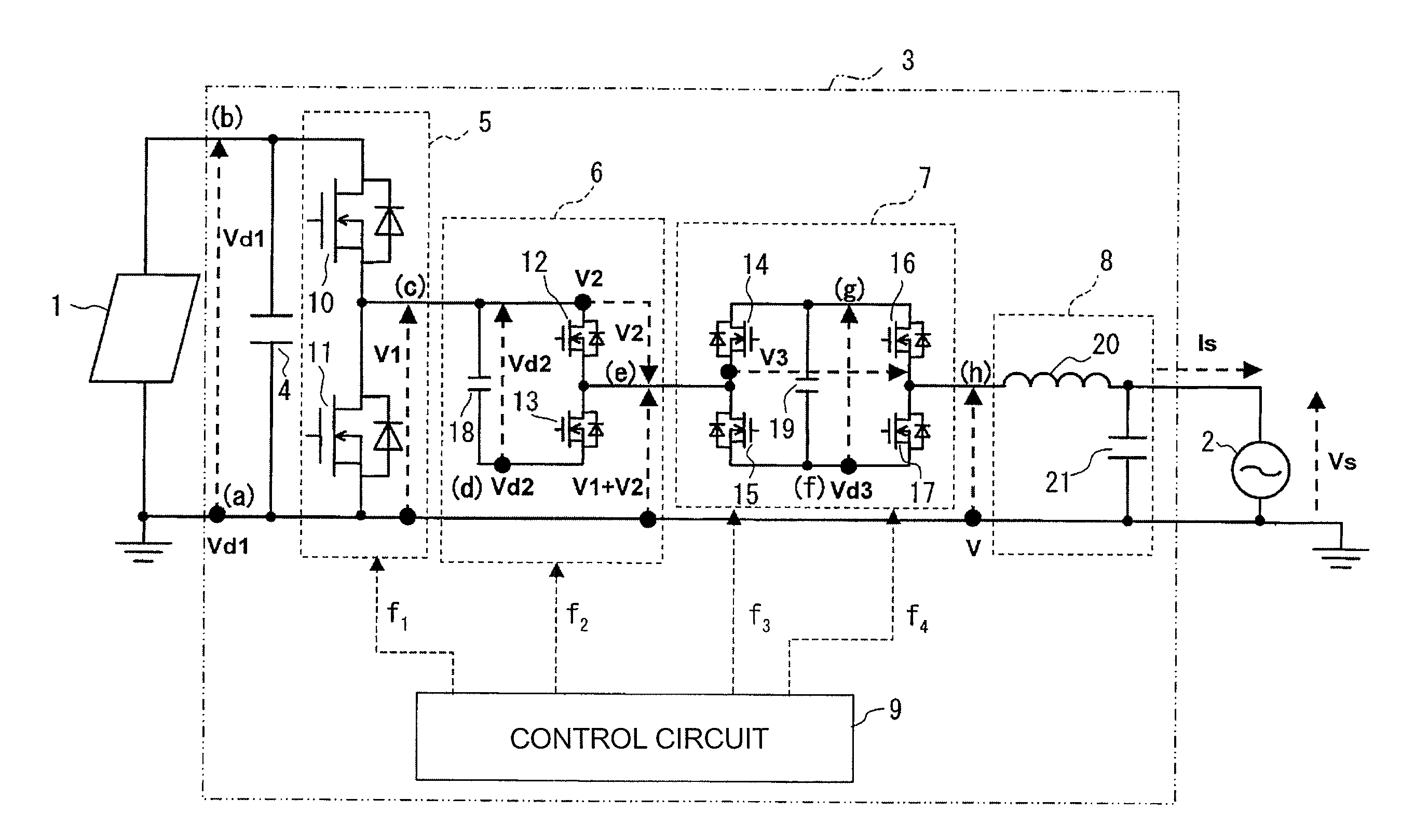
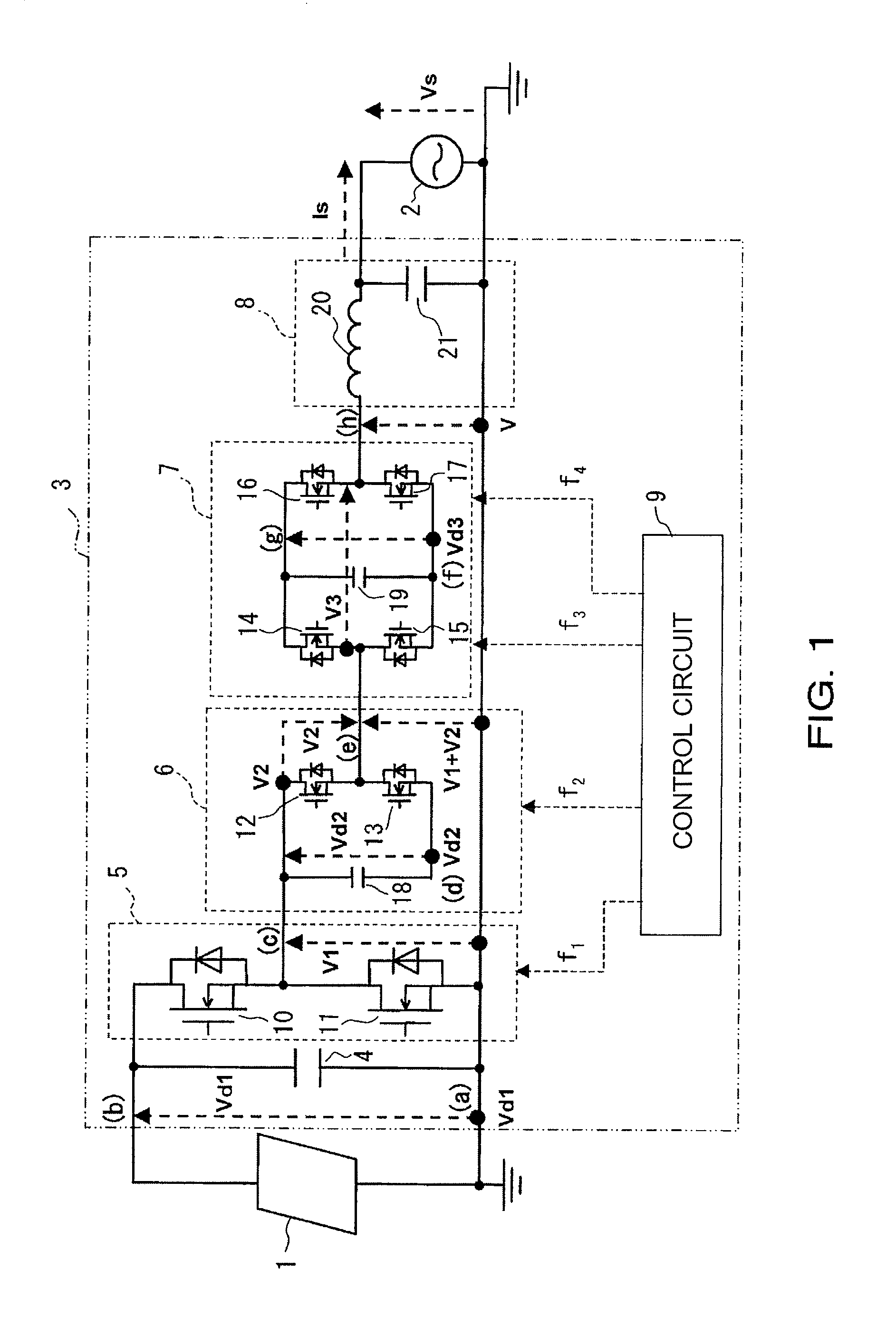
[0054]FIG. 1 is a configuration diagram of a photovoltaic system according to one embodiment of the present disclosure, showing a configuration for a case of single-phase two-wire.

[0055]The photovoltaic system of the embodiment includes a solar cell panel 1, and a power conditioner 3 for converting the DC power from the solar cell panel 1 to the AC power and operating while being interconnected to a commercial power supply 2.

[0056]The solar cell panel 1 is configured by connecting a plurality of solar cell modules in series and in parallel to obtain a desired generated power.

[0057]The solar cell panel 1 of the embodiment is configured by a thin film solar cell made of amorphous silicon.

[0058]The power conditioner 3 of the present embodiment is a non-insulating type (transformer-less) power conditioner not including an insulating transformer.

[0059]The power conditioner ...


PUM


Abstract

A power conditioner of a photovoltaic system is configured operate at higher accuracy. A chopper circuit, a capacitor connected in parallel to the chopper circuit, and a control circuit that controls an ON / OFF status of switch elements in the chopper circuit to control charging and discharging of the capacitor are provided. The control circuit includes a measurement control section that measures an inter-end voltage of the capacitor and a control circuit section that performs a predetermined control operation from a measurement output of the measurement circuit section. The measurement circuit section includes a differential amplifier circuit that differentially amplifies the inter-end voltage of the capacitor. The circuit control section calibrates an in-phase component in the output of the differential amplifier circuit as an in-phase error and performs the control from the calibrated output from the differential amplifier circuit.

Description

CROSS-REFERENCE TO RELATED APPLICATION[0001]This application claims benefit of priority under 35 U.S.C. § 119 to Japanese Patent Application No. P2010-054246 filed on Mar. 11, 2010, which is expressly incorporated herein by reference in its entirety.BACKGROUND[0002]1. Field of the Disclosure[0003]The present disclosure relates to a control circuit, a power conditioner including the control circuit, and a photovoltaic system.[0004]2. Background Information[0005]A photovoltaic system generally converts a direct-current (DC) power from a solar cell to an alternating-current (AC) power of a commercial frequency that is interconnected to a system by a power conditioner and also supplies the converted AC power to an in-house load connected to a commercial power system, where excessive power is reversely flowed to the system side if the AC power is greater than the consumption power of the in-house load. In such a power conditioner, a non-insulating type excelling in power conversion effic...

Claims


Application Information

Patent Timeline
IPC IPC(8): H02M7/539
CPCH02M7/49H02M7/797H02M2007/4835H03F2203/45604H03F3/45475H03F2203/45528H03F2203/45594Y02E10/56H02M7/4835H02M1/0095H02J3/38H02M7/48H02J7/35G05F1/67
Inventor MABUCHI, MASAOMIYAMOTO, MIOMAKI, NAOKINAKAMURA, KOTAROTSUNAGA, AKIYUKI
Owner ORMON CORP
Features
  • R&D
  • Intellectual Property
  • Life Sciences
  • Materials
  • Tech Scout
  • Unparalleled Data Quality
  • Higher Quality Content
  • 60% Fewer Hallucinations
Learn More