
Archery rest system

a technology of rest system and archery, applied in the field of archery rest system, can solve the problems of high mechanical stress placed on the attachment string and the force imparted on the mechanism, failure of the mechanism, wear of the parts, etc., and achieve the effect of relieving the for

Active Publication Date: 2013-10-01
HAMSKEA ARCHERY SOLUTIONS
View PDF14 Cites 26 Cited by
  • Summary
  • Abstract
  • Description
  • Claims
  • Application Information

AI Technical Summary

Benefits of technology

The present invention is an archery rest system for use with a bow. It includes a main body that is mounted to the bow riser and a shaft with a lever arm that is rotatably mounted within the main body. An attachment cord is provided with one end secured to the lever arm and the other end either to the first limb or the second limb of the bow. An in-line dampening spring is mounted between the lever arm and the securing means to absorb the load imparted on the attachment cord when the rotating shaft reaches its rotation travel limit. The main technical effect of this invention is to have a more stable and reliable archery rest system that improves the accuracy and safety of the archery sport.

Problems solved by technology

One of the main problems with limb actuated designs is the stress that is placed on the attachment string and the forces imparted on the mechanism that stops the launcher's travel.
These issues cause several problems: 1) The string stretches causing the tune of the arrow rest to change the arrow's point of impact; 2) the string breaks after repeated cycles as there is no means for absorbing the force imparted by the limb and 3) the lack of force absorption causes high mechanical stresses causing failures and worn parts.
Also, there are many archery rests on the market but none integrate any features that allow the archer's sight to be assessed for third axis adjustment at full draw.

Method used


Image

  • Archery rest system
  • Archery rest system
  • Archery rest system

Examples


Embodiment Construction

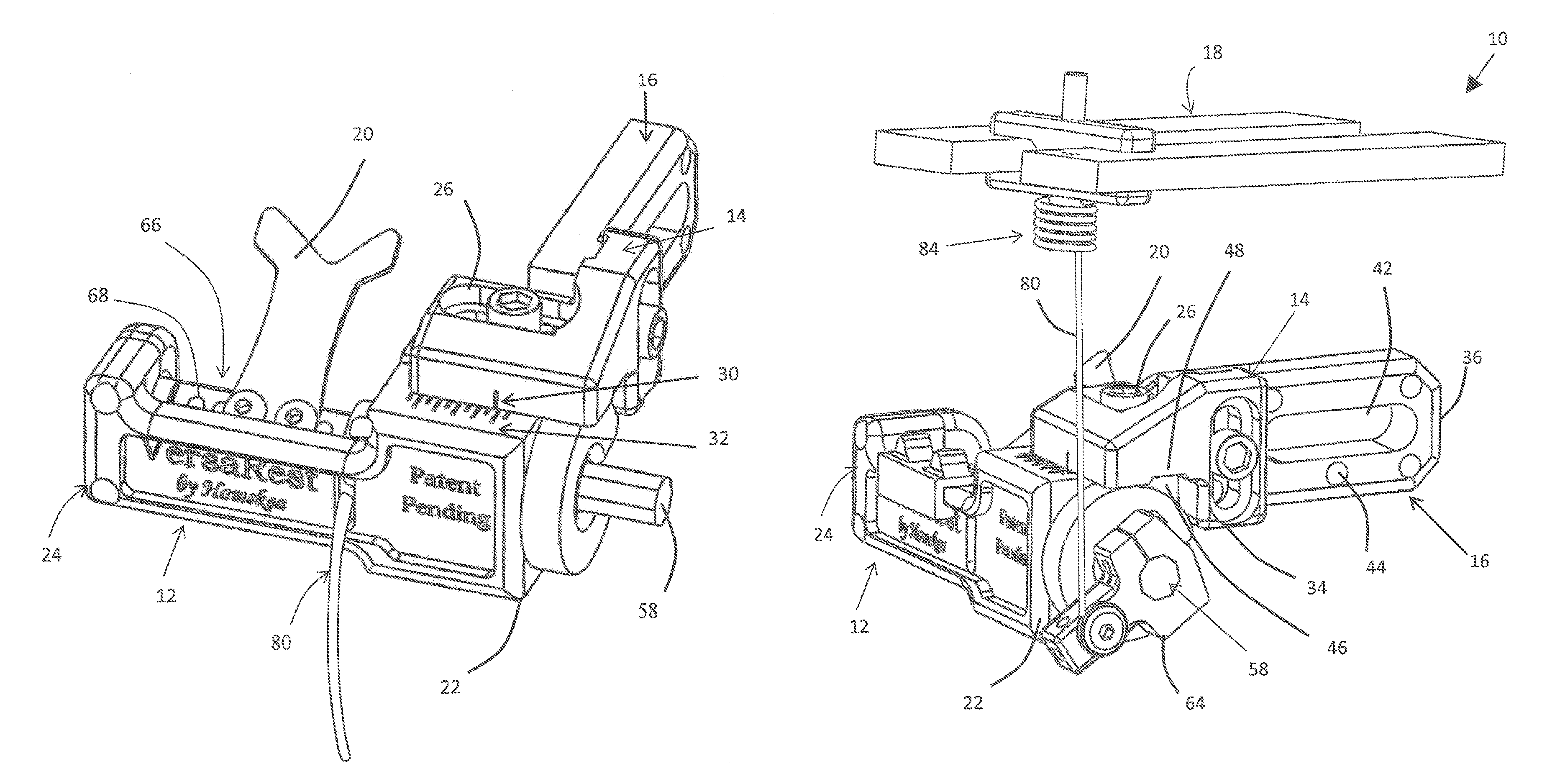
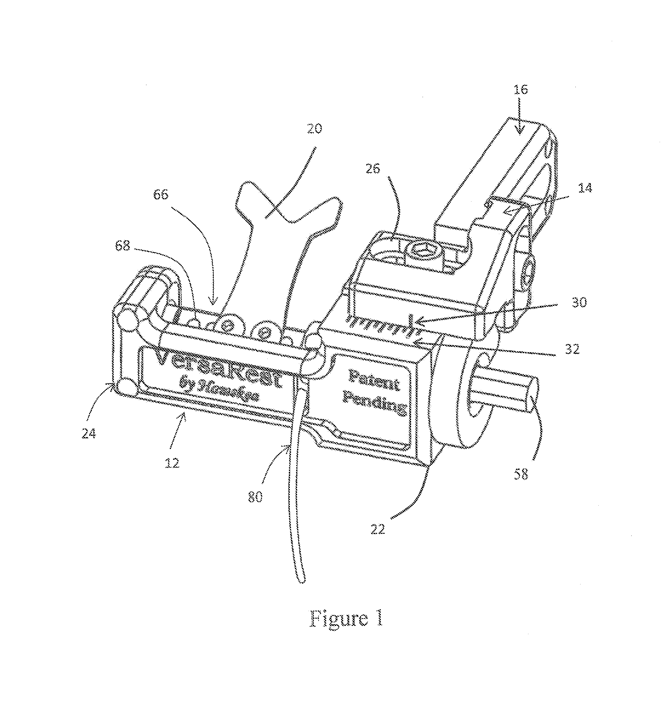
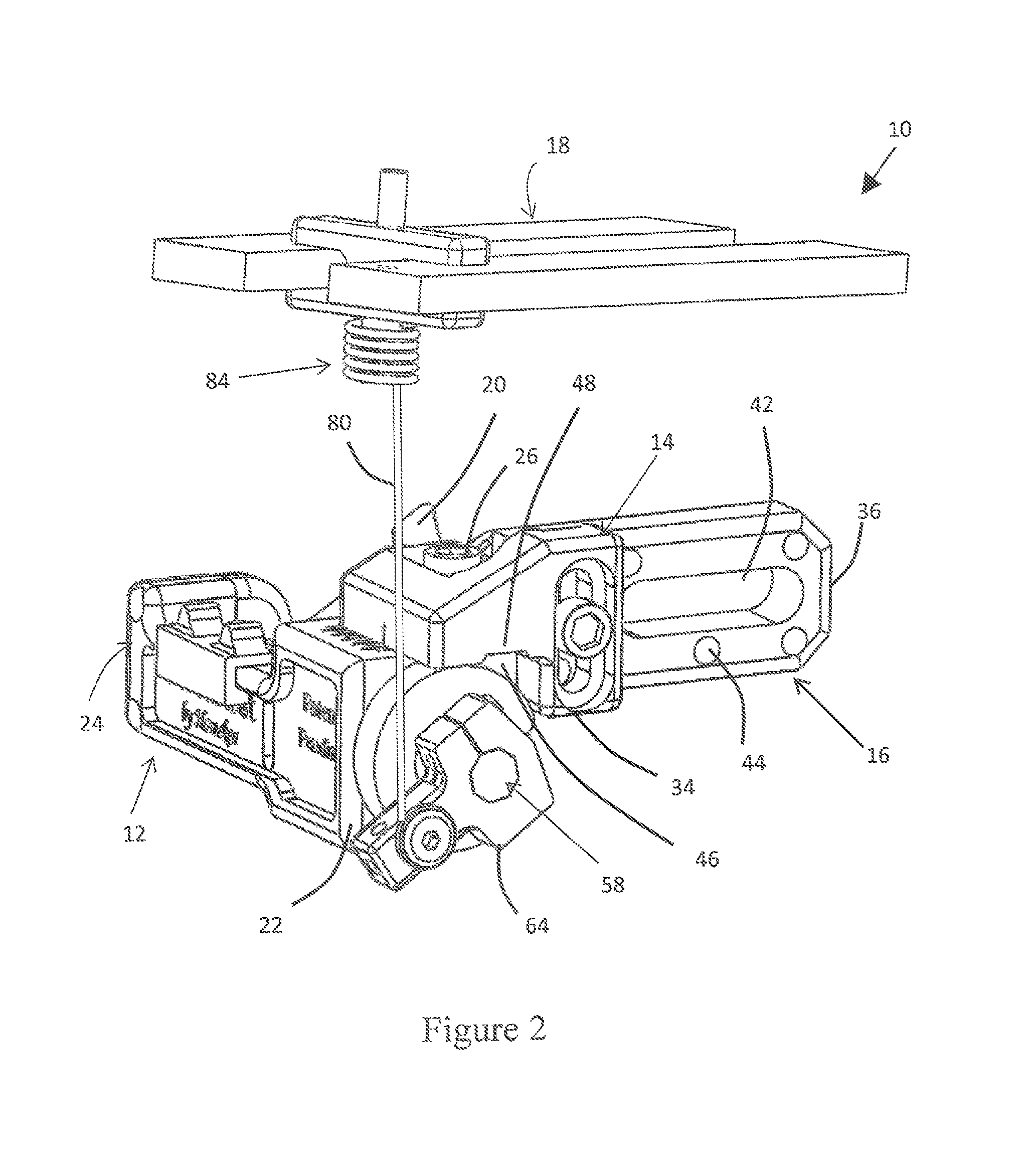
[0028]As illustrated in FIGS. 1-15, the present invention is an archery rest system, indicated generally at 10, providing three styles of rest including a fall away (FIG. 1), limb actuated (FIG. 2), and fixed launcher position (FIG. 3) rest and allowing for assessing the bows sight for third axis alignment. The archery rest system 10 of the present invention provides a means to configure one main assembly arrow rest system 10 into either a fall away, limb actuated or fixed launcher configuration.

[0029]The archery rest system 10 of the present invention comprises a main body 12, an attachment piece 14 slidably secured to the main body 12, an attachment arm 16 slidably secured to the attachment piece 14 for attaching the archery rest system 10 to a bow 18, and an arrow launcher 20. The main body 12 has a first end 22 and a second end 24 with the attachment piece 14 slidably connected adjacent the first end 22 of the main body 12. The attachment piece 14 has a first slot 26 with a firs...


PUM


Abstract

An archery rest system comprises a body mounted to the bow. A shaft is mounted within the body and a lever arm is secured to the shaft. An opening is formed in the body with an arrow launcher mounted to the shaft and extending through the opening. A spring biases the arrow launcher in an up position. A cord is secured to the lever arm. A securing mechanism secures the cord to the bow and an in-line dampening spring is mounted between the lever arm and the securing mechanism. With the bow at rest, the launcher moves to a down position out of contact with the arrow. Upon bow draw, the launcher moves into the up position contacting the arrow. Upon bow firing, the launcher moves to the down position with the spring absorbing load imparted on the cord when the shaft reaches a rotation travel limit.

Description

[0001]The present application is a continuation of provisional patent application Ser. No. 61 / 460,215, filed on Dec. 28, 2010, entitled “Archery Rest”.BACKGROUND OF THE INVENTION[0002]1. Field of the Invention[0003]This invention relates generally to an archery rest system and, more particularly, the invention relates to an archery rest system providing three styles of rest including a fall away, limb actuated, and fixed launcher position rest and allowing for assessing the bows sight for third axis alignment (reference U.S. Pat. No. 7,975,391).[0004]2. Description of the Prior Art[0005]Archers have always looked for ways to further increase the accuracy of the archery system (bow, arrows, string, arrow rest, sight aides, stabilizers and operator). Specific to arrow rests, arrow fletching clearance has been an area that introduces arrow flight imbalances if the fletchings of the arrow come in contact with the arrow rest launcher or any bow structure like the riser or string / cables. ...

Claims


Application Information

Patent Timeline
Patent Type & Authority Patents(United States)
IPC IPC(8): F41B5/22
CPCF41B5/143
Inventor MUNSELL, ANDREWGILLINGHAM, TIMOTHY JGREATHOUSE, SHAWN A.
Owner HAMSKEA ARCHERY SOLUTIONS
Learn More