Battery cooling system

a battery and cooling system technology, applied in the field of battery cooling systems, can solve the problems of reducing the life of the battery and contributing to the total weight of the battery, and achieve the effects of simple, lightweight and cost-effectiv

Active Publication Date: 2013-10-08
HANON SYST
View PDF12 Cites 0 Cited by
  • Summary
  • Abstract
  • Description
  • Claims
  • Application Information

AI Technical Summary

Benefits of technology

[0012]In concordance and agreement with the present disclosure, a simple, lightweight, and cost-effective battery cooling system, which is capable of cooling the battery modules while minimizing a required installation space, is surprisingly discovered.
[0013]The problem of known cooling systems is solved by a battery cooling system of the present invention that includes a battery, two battery cooler pipes, and a clamping element that forces the battery cooler pipes against the battery for thermal contact. In certain embodiments, the battery cooler pipes are substantially parallel, distanced to each other and longitudinally arranged at the battery, when the battery is substantially rectangular-shaped. The clamping element is configured as a center portion and two clamping wings extending from both sides of the center portion. Each clamping wing contacts a battery cooler pipe in longitudinal extension. In this way the battery cooler pipe, to a preferred embodiment configured as a flat pipe, is over its whole length forced against the battery and, appropriate forcing provided, the heat loss of the battery can be absorbed over a relatively large surface of the flat pipes.
[0028]For large tolerances of the installation space and the battery modules it can be advantageous to plastically deform the spring sheet on the first assembly, or deliberately allow a plastic deformation, respectively.
[0031]For spans longer than about 200 mm, an additional reinforcement by a separate carrier is advantageous. Using an additional carrier allows more exact adaptation of a spring characteristic of the spring sheet to the contact forces.
[0032]In an advantageous embodiment of the invention, the clamping wings of the clamping element with slits normal to the longitudinal axis are provided. So individual sections are formed that are flexible independent of each other. The flat pipes being highly flexible adapt very well to surface irregularities of the batteries. The individual flexible sections of the clamping wings act as single springs, thereby leading to an even better adaptation of the flat pipes to the battery surface.
[0033]In the invention, the advantages of a very low weight and little installation space, combine with a possibility to realize, also for relatively large dimensional tolerances of the components, constant forcing of the battery cooler pipes to the battery.

Problems solved by technology

In most cases, a plurality of battery modules is employed that use electrochemical principles of oxidation with an electrolyte, thereby producing heat losses.
Generally, the current concepts for forcing the battery cooler to the battery modules require significant installation space are very heavy, strongly contributing to a total weight of the battery.

Method used


Image

  • Battery cooling system
  • Battery cooling system
  • Battery cooling system

Examples


Embodiment Construction

[0040]The following detailed description and appended drawings describe and illustrate various embodiments of the invention. The description and drawings serve to enable one skilled in the art to make and use the invention, and are not intended to limit the scope of the invention in any manner.

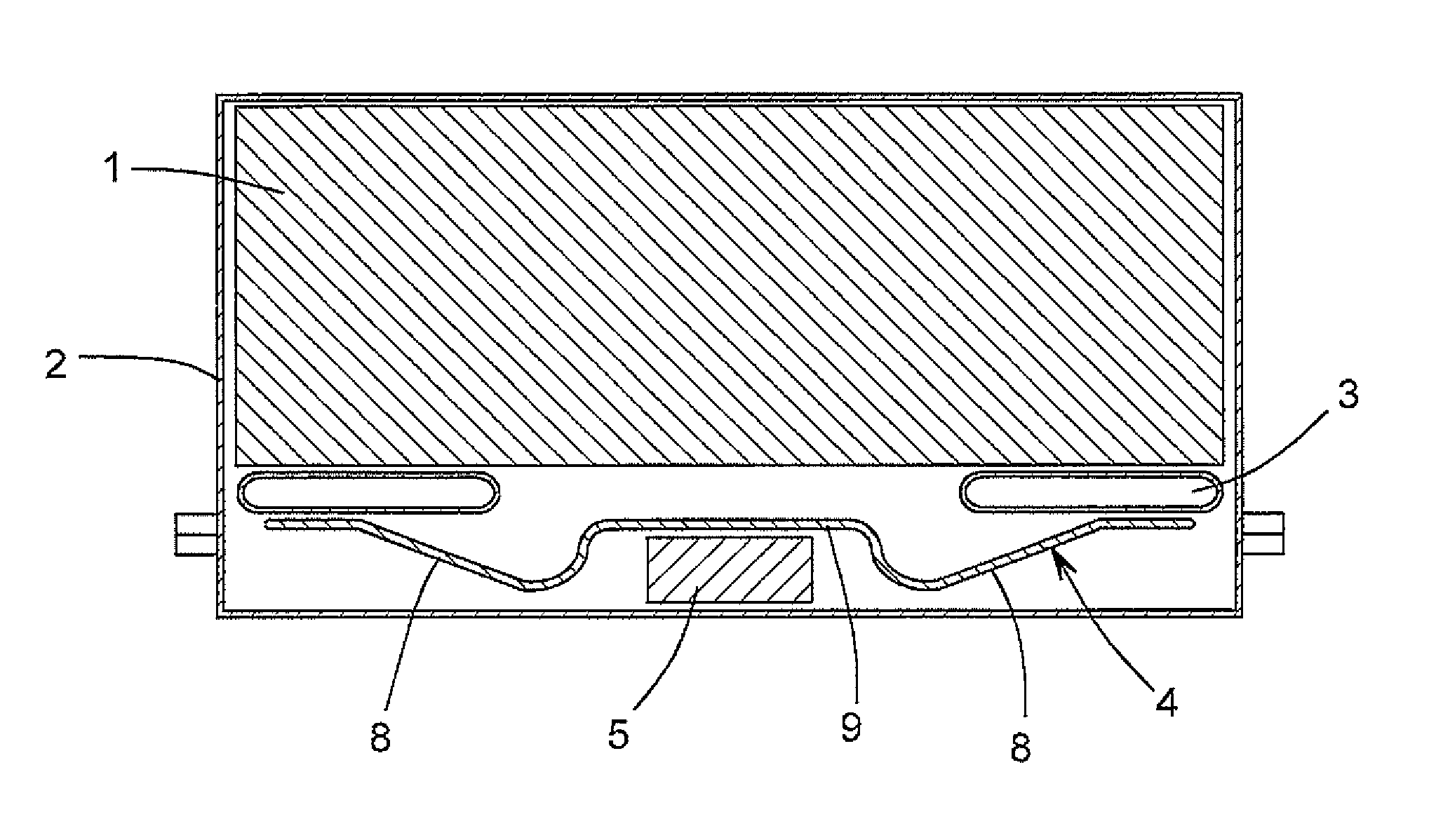
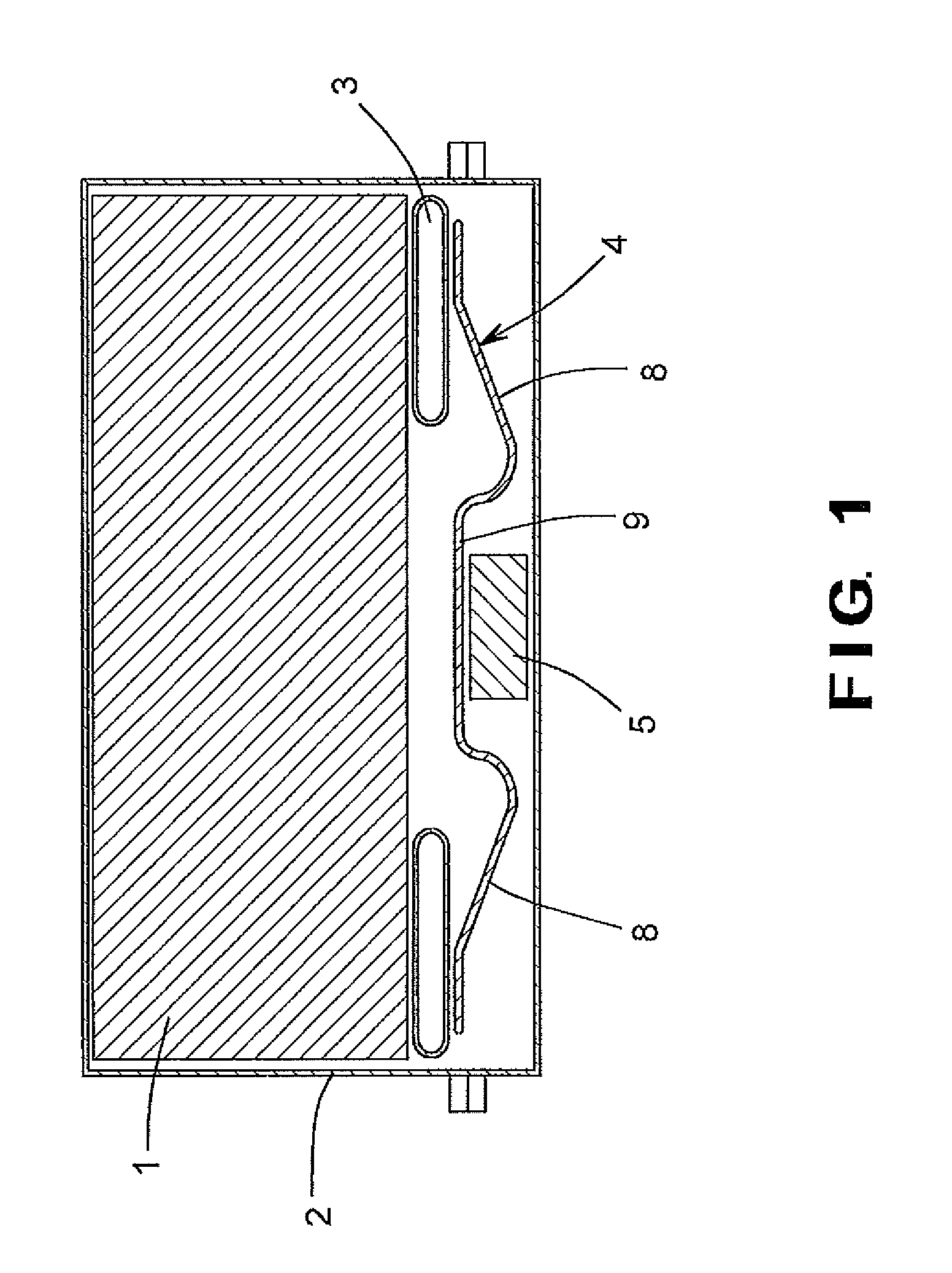
[0041]FIG. 1 shows a battery cooling system in cross-sectional view. The cross-sectional image shows a fundamental structure of the battery cooling system, wherein a clamping element 4 shown is a spring sheet 4 that urges battery cooler pipes 3 against a battery or battery modules 1. During installation of the battery modules 1, the battery cooler pipes 3, and the spring sheet 4 into the battery casing 2, the spring sheet 4 is pre-stressed. A pre-stressing of the spring sheet 4 ensures a constant urging in a longitudinal direction of the battery cooler pipes 3 towards the battery 1.

[0042]When a length of the spring sheet 4 spans more than 200 mm, the particular embodiment of the invention show...


PUM

PropertyMeasurementUnit
lengthaaaaaaaaaa
thicknessaaaaaaaaaa
thicknessaaaaaaaaaa

Abstract

A battery cooling system includes a battery and a plurality of battery cooler pipes disposed adjacent the battery. Each of the battery cooler pipes is spaced apart and substantially parallel to an adjacent one of the battery cooler pipes. A clamping element is disposed adjacent at least one of the battery cooler pipes. The clamping element configured to urge the battery cooler pipes against at least a portion of the battery. The clamping element includes a plurality of clamping wings extending outwardly from a center portion of the clamping element. Each of the clamping wings of the clamping element is disposed adjacent at least one of the battery cooler pipes. The battery cooling system may further include a carrier disposed adjacent the center portion of the clamping element to absorb spring forces of the clamping wings.

Description

CROSS-REFERENCE TO RELATED APPLICATION[0001]This application claims the benefit of German Provisional Patent Application No. DE 10 2011 053 835.6 filed Sep. 21, 2011 and German utility Patent Application No. DE 20 2012 102 969.3 filed Aug. 7, 2012, the entire disclosures of which are hereby incorporated herein by reference.FIELD OF THE INVENTION[0002]The invention relates to a battery cooling system provided with a battery cooler pipe that for improved thermal contact is forced against a battery or a battery module of a motor vehicle, exerting a homogeneous contact force.BACKGROUND OF THE INVENTION[0003]In electric energy stores, devices for a voltage supply of motor vehicles such as electro vehicles or hybrid vehicles, usually known as batteries. In most cases, a plurality of battery modules is employed that use electrochemical principles of oxidation with an electrolyte, thereby producing heat losses.[0004]A stack of individual battery modules is clamped, oftentimes, over a mechan...

Claims


Application Information

Patent Timeline
Patent Type & Authority Patents(United States)
IPC IPC(8): H01M2/14H01M2/18
CPCH01M10/5004H01M10/5061H01M10/613H01M10/656Y02E60/10
Inventor KOESTER, STEPHANGIRMSCHEID, FELIXEMMERICH, ANDREASTALMON, JENS
Owner HANON SYST
Why Eureka
Try Eureka