Apparatus for measuring the position of a vehicle or a surface thereof

a technology for measuring apparatuses and vehicles, applied in the direction of measuring devices, using reradiation, instruments, etc., can solve the problems of limited accuracy of position measurement of such radar systems, limited service life and temperature range of systems, and high processing effort of vehicle speeds, so as to achieve more cost-effective effects

Inactive Publication Date: 2014-11-13
KAPSCH TRAFFICCOM AG
View PDF49 Cites 21 Cited by
  • Summary
  • Abstract
  • Description
  • Claims
  • Application Information

AI Technical Summary

Benefits of technology

[0008]An object of the disclosed subject matter is to create novel apparatus and methods for measuring the position of vehicles and / or surfaces thereof, said apparatus and methods being less susceptible to failure than the known optical systems and being simpler, more cost effective and more accurate than the known radar systems.

Problems solved by technology

These systems are reliant on good visibility and are therefore highly dependent on the weather; they often fail in rain, snow or spray.
The optics of laser scanners and video cameras also requires frequent cleaning in order to remain ready for use, and these systems have a limited service life and a limited temperature range due to mechanically moved parts.
The accuracy of the position measurement of such radar systems is limited, and the Doppler evaluation of the vehicle speeds requires a high processing effort in order to create the traffic flow image.

Method used


Image

  • Apparatus for measuring the position of a vehicle or a surface thereof
  • Apparatus for measuring the position of a vehicle or a surface thereof
  • Apparatus for measuring the position of a vehicle or a surface thereof

Examples


Embodiment Construction

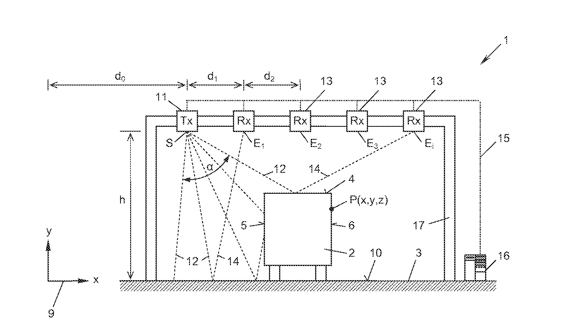
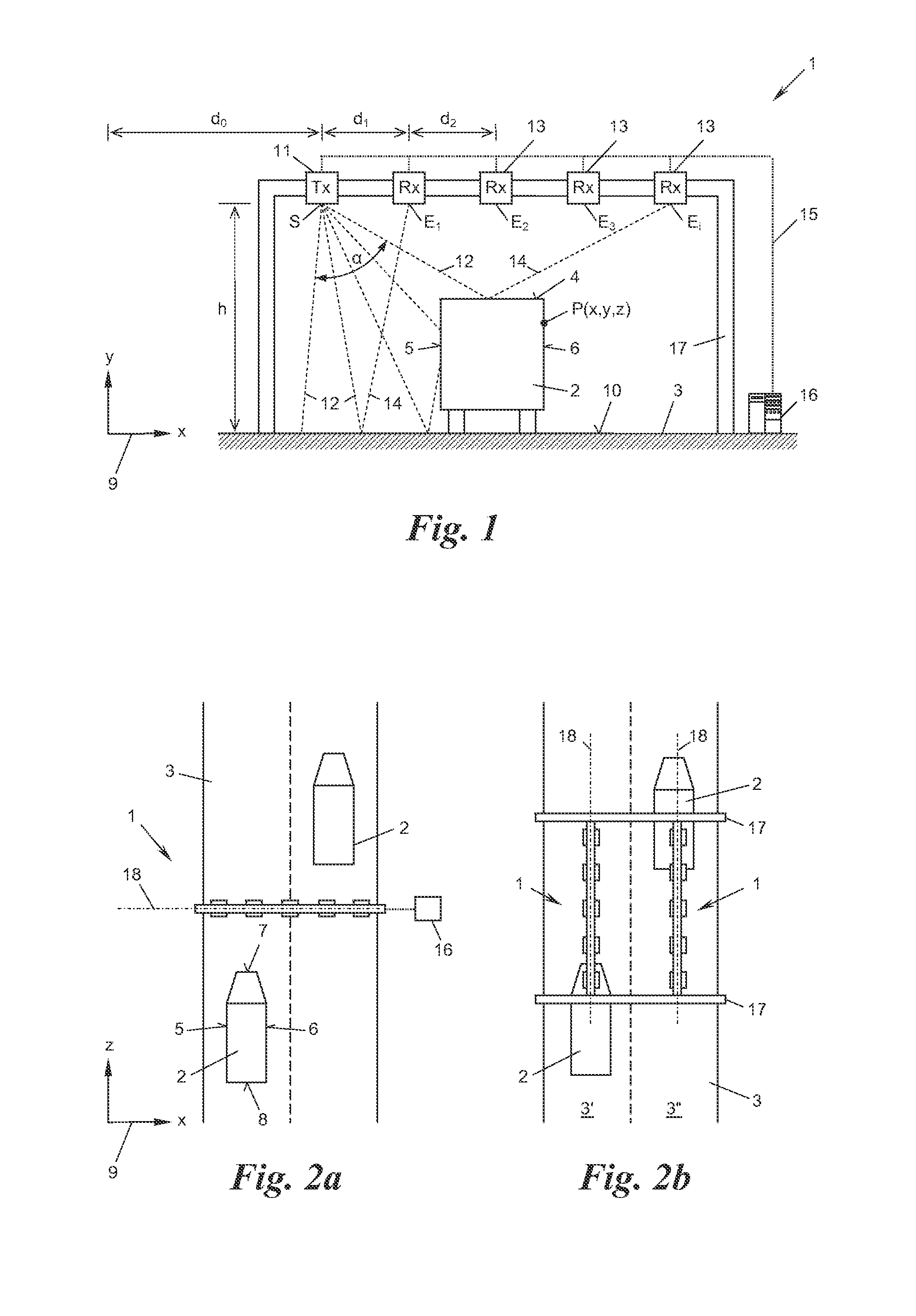
[0036]An apparatus 1 for measuring the position of a vehicle 2 on a roadway 3 is shown in FIGS. 1 and 2a. The term “position” is understood here in its most general form and includes one, two or three of the coordinates x, y, z of any point P of the vehicle 2 or one of the surfaces thereof, for example a roof 4, side face 5, 6 or end face 7, 8, in a coordinate system 9. The coordinate system 9 is may, for example, be based on the position of the apparatus 1 with respect to the roadway 3; in the present example the plane 10 of the roadway 3 lies in the x / z plane of the coordinate system, the longitudinal direction of the roadway runs in the z direction, and the transverse direction of the roadway runs in the x direction; the y coordinate defines the height of a point P above the roadway plane 10.

[0037]The apparatus 1 comprises a radar transmitter 11, which is arranged in a transmitting position S above the plane 10 of the roadway 3 and transmits radar beams 12 downwardly, and also a ...


PUM


Abstract

An apparatus is disclosed for measuring the position of a vehicle or a surface thereof on a roadway. The apparatus comprises at least one radar transmitter, which is arranged in a transmitting position above the plane of the roadway and transmits radar beams downwardly, a plurality of radar receivers, which are distributed above the plane of the roadway in different receiving positions at distances from one another, receive reflections of the radar beams from beneath, and convert the reflections into a received signal, and an evaluation device, which is connected to the radar transmitter and the radar receivers and is configured to measure the said position from the transmitting position, the receiving positions and the received signals.

Description

CROSS-REFERENCE TO RELATED APPLICATION(S)[0001]This application claims priority to European Patent Application No. 13 167 404.6, filed on May 13, 2013, the entirety of which is incorporated by reference herein.BACKGROUND[0002]1. Technical Field[0003]The present subject matter relates to an apparatus for measuring the position of a vehicle or a surface thereof on a roadway.[0004]2. Background Art[0005]The measurement of the position of vehicles is important for many tasks in the field of traffic control, traffic monitoring and traffic billing, for example in order to determine the lane used by a vehicle at an electronic traffic control point or tollbooth or also in order to identify the longitudinal position of a vehicle along the roadway so as to be able to assign the vehicle unambiguously to the image of a traffic monitoring camera. The measurement of the position of a surface of the vehicle, for example the roof or side faces thereof, is of significance in order to determine the s...

Claims


Application Information

Patent Timeline
Patent Type & Authority Applications(United States)
IPC IPC(8): G01S7/02G01S7/28G01S13/06
CPCG01S7/02G01S13/06G01S7/28G01S13/003G01S13/48G01S13/878G01S13/91G07B15/06G08G1/015G01S7/292G01S7/41G08G1/01
Inventor NAGY, OLIVER
Owner KAPSCH TRAFFICCOM AG
Why Eureka
Try Eureka