Apparatus and method for mixing dissimilar fluids

a technology of dissimilar fluids and apparatus, which is applied in the field of fluid mixing, can solve the problems of increasing the agitation of the mixture, and achieve the effects of improving the mixing of the fluid, enhancing cavitational disturbance, and efficient mixing

Inactive Publication Date: 2008-01-08
THOMA CHRISTIAN
View PDF44 Cites 60 Cited by
  • Summary
  • Abstract
  • Description
  • Claims
  • Application Information

AI Technical Summary

Benefits of technology

[0009]It is therefore a feature of the invention that the initially quite separate fluids inputs to the device are disposed at two quite independent entry locations, both preferably located in the housing, such the fluids combine interiorly and not exteriorly of the housing. Preferably, the fluids combine in the volumetric region bounded between the static housing and the revolving rotor on the one hand, and on the other hand, at or near to the location of the said at least one array of surface irregularities disposed on the surface on the rotor. As such, the quite separate streams of fluid entering via the housing to the internal chamber of the device can be said to be initially spaced apart at the rotor surface by this array of surface irregularities, combining fully only after one of the fluids has travelled past that distance covered by the array of surface irregularities in a direction towards the fluid output or exit of the machine. Preferably, additional arrays of bottom-end holes may be employed over the remaining surface of the rotor for improve the mixing of the fluids. If deployed, such additional arrays produce more enhanced cavitational disturbances resulting in increased agitation of the mixture as it travelling along common path towards the exit to depart the device as a refined and homogeneous mixture.
[0010]Although it is most normal that the dissimilar fluids admitted to the machine will be pressurized above atmospheric pressure in order to flow more readily through the device, it is a preferred feature of the invention to input the fluids into the chamber nearer the rotational axis of the machine and incorporate the peripheral exit for the mixture nearer towards the external diameter dimension of the rotor. It is a further preferred feature that the rotational energy imparted to each of the fluids by the revolving rotor in itself acts to help prevent the fluids flowing in the wrong direction, thus for many applications, alleviating the need for having check valves. Furthermore, the shape of the rotor may also, when required, be used as a further means to help propel the fluid mixture through the interior of the device such that less reliance may be placed on the supply pressure of the fluids. For example, by inclining the surface of the rotor with respect to the rotational axis, a small pumping effect is produced which can help the mixture move in a direction towards the periphery exit.
[0011]Various rotor shapes are disclosed in this specification and where surface irregularities are shown as parallel bottom-ended holes. However, such surface irregularities may be modified and be short-circuited back into one of the two fluid input streams to create additional cavitation in the mixing liquids. During high speed rotation of the rotor, such bottom-ended holes create low pressure zones in and about the passing liquids. The fluids are squeezed and expanded by the vacuum pressure and the condition of cavitation together with accompanying shock wave behaviour producing sufficient turbulence to ensure a good mixing between the once dissimilar fluids. In the case of municipal waste water treatment plant, as the rate at which the biological digestion of the organic matter pollutants takes place is especially dependent on the quantity of oxygen carried in the waste water, the more oxygen available in the water to sustain the activity of the micro-organisms in consuming the pollutants, the more cost-effective the process for the tax payer, and for the betterment for the environment.

Problems solved by technology

If deployed, such additional arrays produce more enhanced cavitational disturbances resulting in increased agitation of the mixture as it travelling along common path towards the exit to depart the device as a refined and homogeneous mixture.

Method used


Image

  • Apparatus and method for mixing dissimilar fluids
  • Apparatus and method for mixing dissimilar fluids
  • Apparatus and method for mixing dissimilar fluids

Examples


Embodiment Construction

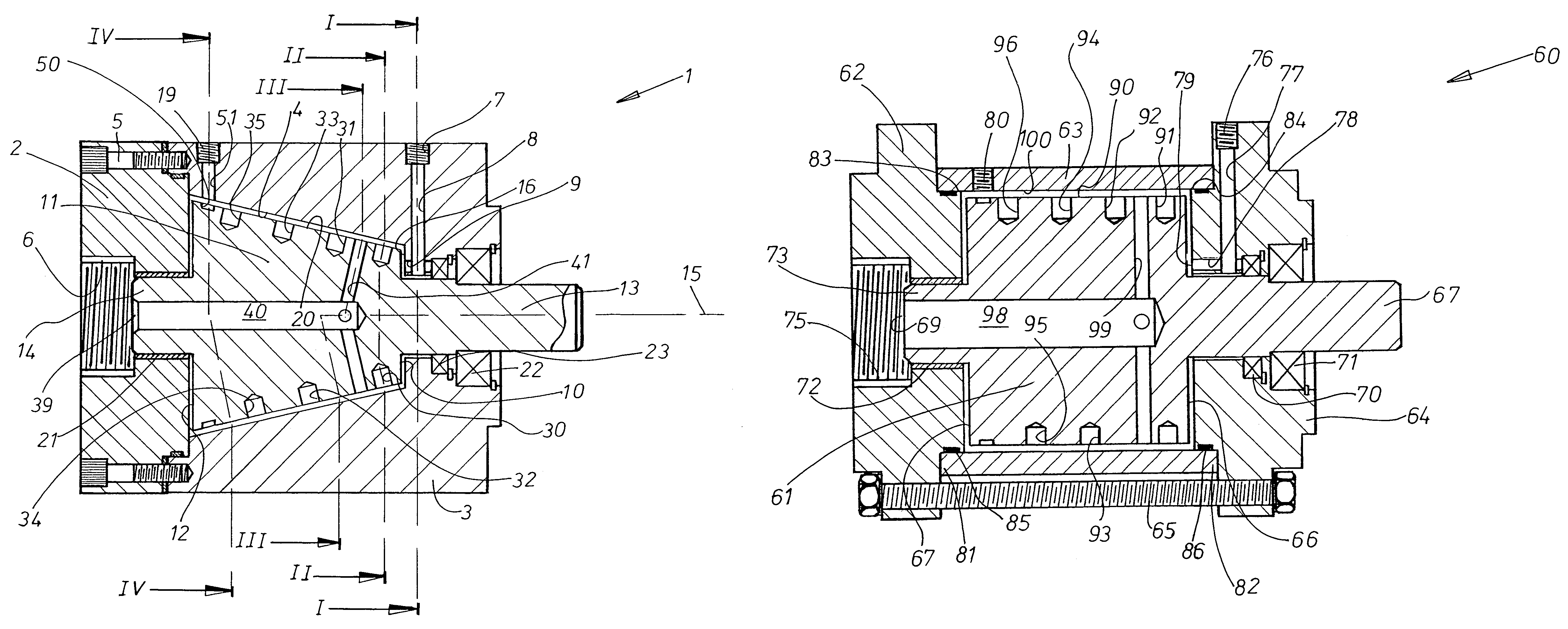
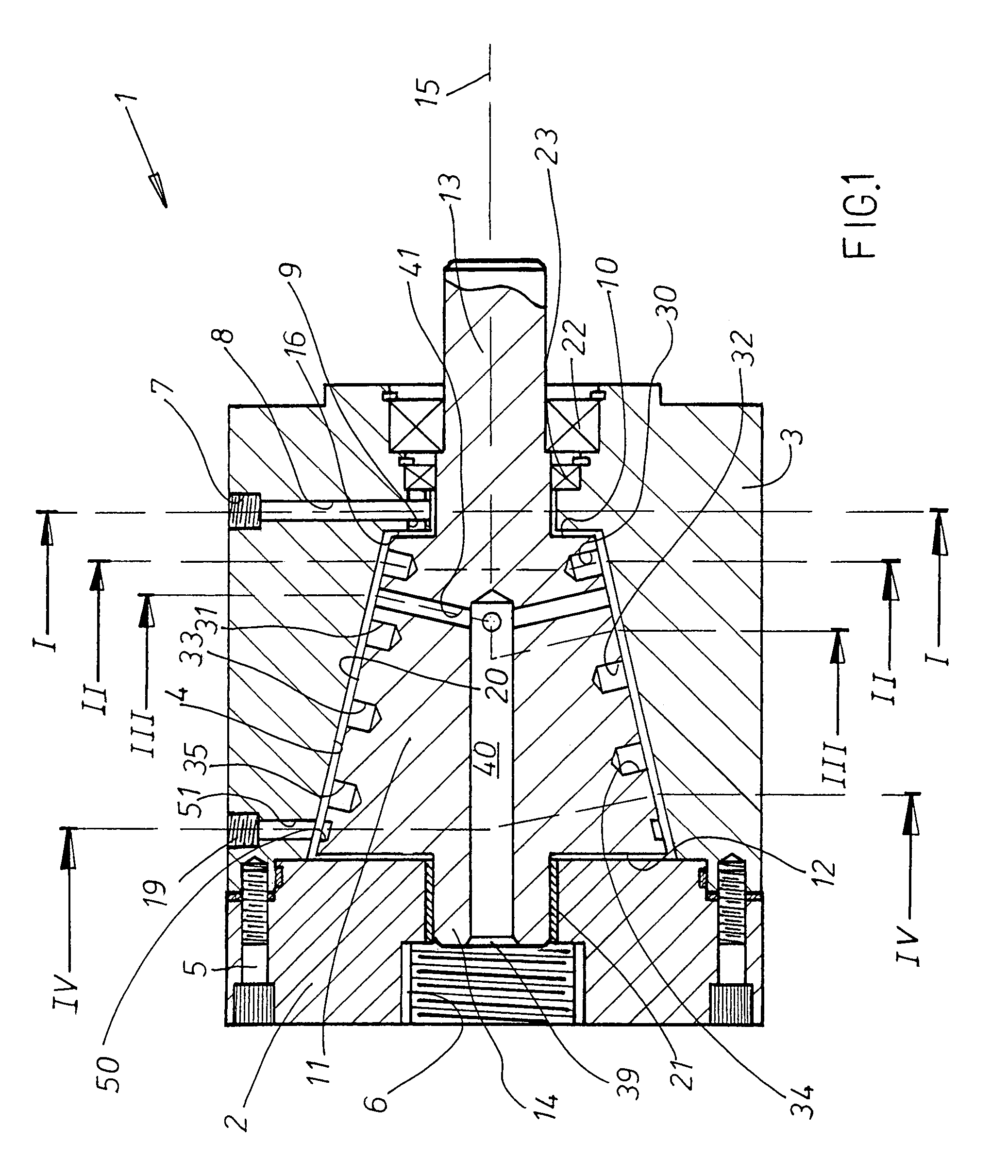
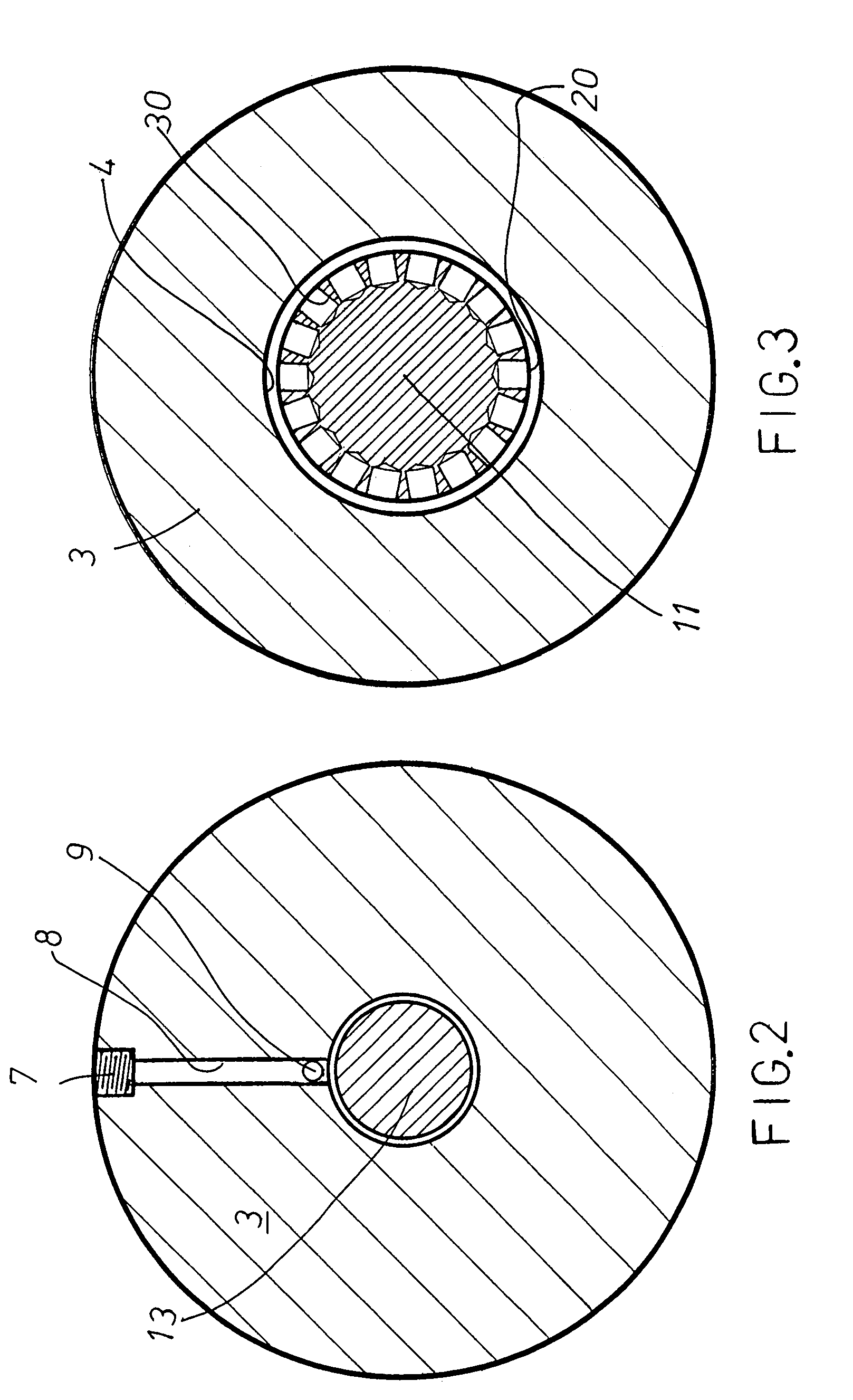
[0032]Referring to FIGS. 1 and 5, the device denoted by reference numeral 1 shows a housing structure comprising a rear housing member 2 and a front housing member 3. Housing member 3 is produced with a central main bore 4 which forms the main chamber of the device 1 once housing member 2 is attached to it and the housings members 2, 3 are held together by a series of screws 5. Rear housing member 2 is provided with a threaded central fluid intake connection 6 for fluid ‘A’ and front housing member 3 is provided with a threaded fluid intake connection 7 for fluid ‘B’.

[0033]The rotatable unit comprises a rotor portion 11 positioned in central main bore 4 and extending in length from the smaller diameter end 10 to larger diameter end 12, as well shaft portions 13, 14. Shaft portion 13 extends out from housing member 3 to provide means for driving the device 1, for instance by a prime mover such as an electric or diesel motor, whereas shaft portion 14, extending from larger diameter en...


PUM

PropertyMeasurementUnit
gap heightaaaaaaaaaa
surface lengthaaaaaaaaaa
travel distanceaaaaaaaaaa

Abstract

An apparatus and method for fluid mixing comprising a housing having an internal chamber and a rotatable unit disposed in the chamber. Sufficient clearance is provided between the rotatable unit and the housing to create space for the mixing of the two or more dissimilar fluids. As one example, one fluid input arrives in the mixing chamber by suitable ducting in the housing and the other fluid input arrives in the mixing chamber via a passage in the rotatable unit, the fluids collide and mix and where preferably at least one array of surface irregularities are disposed on an exterior face of the rotatable unit. The refined fluid mixture leaves the apparatus from a exit in the housing preferably poritioned radially outwardly of the rotatable unit.

Description

BACKGROUND OF THE INVENTION [0001]This invention relates generally to fluid mixing, and more particularly, to a method and apparatus for mixing dissimilar liquids and dissimilar fluids such as a gas and a liquid or dissimilar liquids; and specifically to those devices wherein rotating elements are employed to mix the fluid passing through them. Although there are numerous applications requiring mixing apparatus, one such application is for the clarification of waste water, where the waste water and air are to be mixed together in order that the pollutants carried in the waste water can be broken down through being decomposed by oxidation. Conventional mixing apparatus usually employ some form of shaft-driven impeller arrangement located within a chamber in which the fluids are introduced. Such apparatus, however, often provides a poor quality product mix and are therefore not always the best solution for an intended application. Other types employ rotating drums or rotors, where the...

Claims


Application Information

Patent Timeline
Patent Type & Authority Patents(United States)
IPC IPC(8): B01F15/00B01F3/04B01F7/00
CPCB01F3/04531B01F7/00775B01F7/00783B01F7/00816B01F7/00825B01F7/007B01F2215/0052B01F23/233B01F27/2122B01F27/2712B01F27/2713B01F27/2722B01F27/2723B01F2101/305
Inventor THOMA, CHRISTIAN
Owner THOMA CHRISTIAN
Why Eureka
Try Eureka