Programmable power supply system

a power supply system and programmable technology, applied in logic circuits, instruments, liquid/fluent solid measurements, etc., can solve the problems of multiple power supplies, prior art module standards have not addressed the need for multiple electrical signaling standards, etc., to achieve low core power supply voltage, increase density and performance, and low cost

Inactive Publication Date: 2005-04-28
NALLATECH
View PDF6 Cites 63 Cited by
  • Summary
  • Abstract
  • Description
  • Claims
  • Application Information

AI Technical Summary

Benefits of technology

[0015] According to one embodiment, this invention provides a flexible modular standard for implementing digital systems using FPGAs. In further embodiment of this invention provides support for the complex power supply requirements of modern FPGAs. The invention also provides support for systems built from FPGAs and other components with differing power supply requirements.
[0016] Among the advantages of a preferred embodiment of this modular system are: (1) New FPGAs using a more modern process technology and a corresponding lower core power supply voltage are compatible with previous systems allowing users to take advantage of their increased density and performance. (2) The modular daughtercards remain simple and relatively low cost since programmable power supplies are provided on the baseboard. This makes upgrading the system more cost effective.

Problems solved by technology

Since a system is normally built from many different types of integrated circuits supplied by different vendors it is very likely that there will be multiple power supplies required and multiple voltage level standards for interchip signaling.
Prior art module standards have not addressed the need for multiple electrical signaling standards or the requirement for modules to operate off different supply voltages.

Method used


Image

  • Programmable power supply system
  • Programmable power supply system
  • Programmable power supply system

Examples


Embodiment Construction

[0041] In the following description, for the purposes of explanation, specific numbers, materials, component part numbers, and configurations are described in order to provide a thorough understanding of the invention. However, it will be apparent to one skilled in the art that the present invention may be practiced without the specific details. In other instances, well known features are omitted or simplified in order not to obscure the present invention.

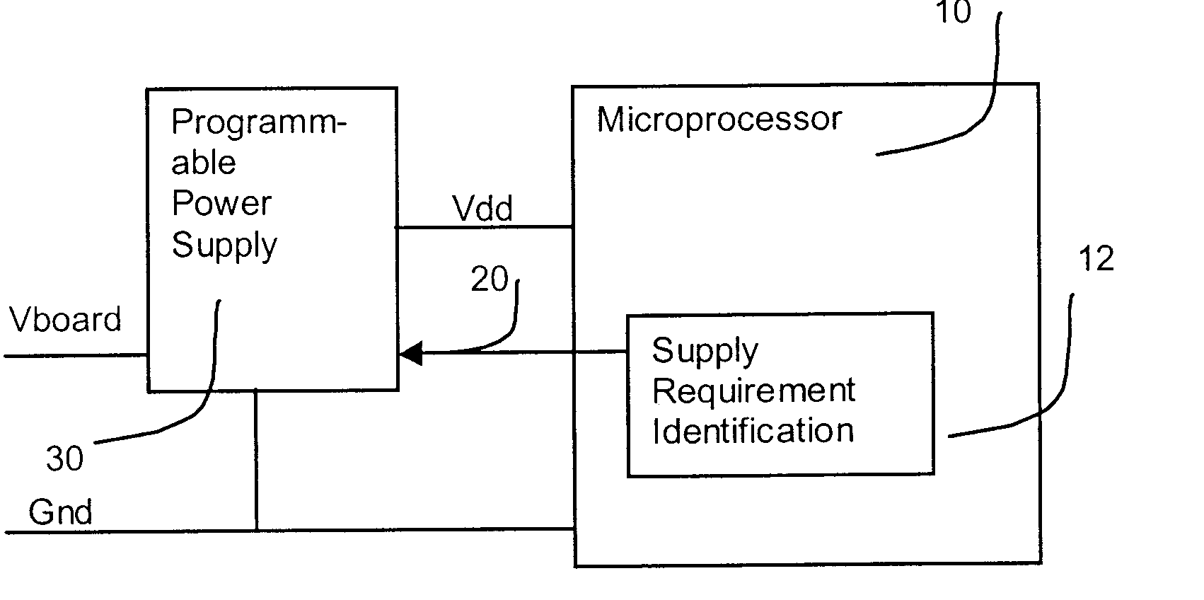
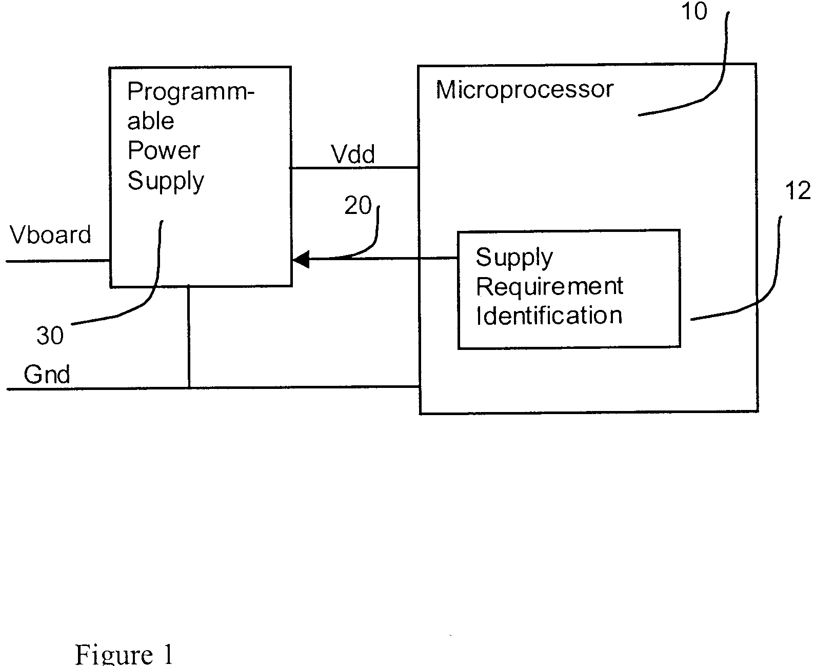
[0042] Programmable Power Supply for Integrated Circuits

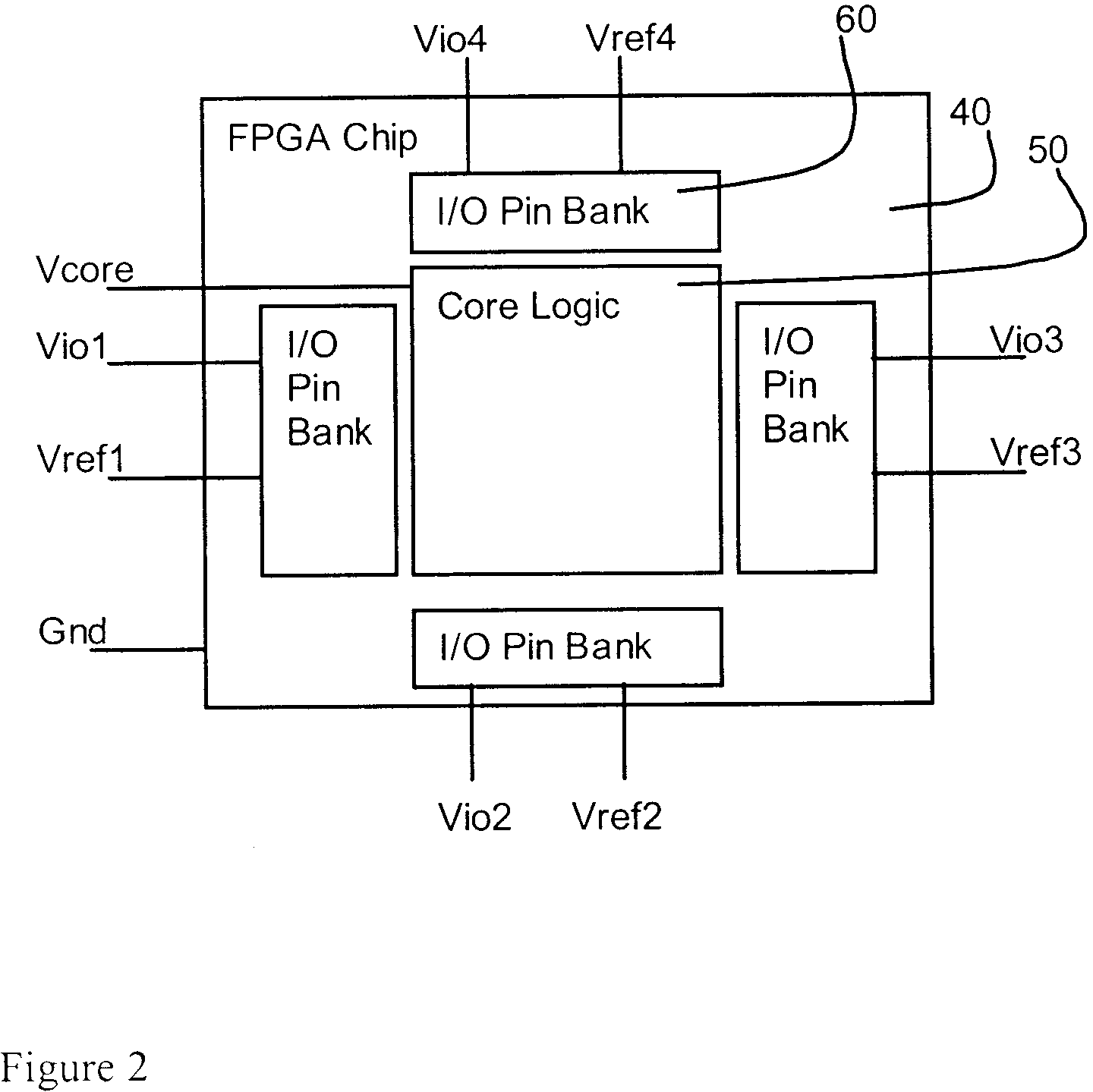
[0043]FIG. 3 shows one embodiment of a programmable power supply for FPGA chips according to this invention. Although described with respect to FPGAs and programmable logic, the invention may be applied, with the appropriate modifications, to other types of integrated circuits including memories, ASICs, microprocessors, and controllers, as well as combinations of these. FPGAs and programmable logic is also sometimes referred to as programmable logic devices (PLDs), programma...


PUM


Abstract

A module standard for integrated circuit such as FPGAs is provided in which power supply voltages for daughtercards are not fixed in advance. Instead programmable power supplies are provided and a method is provided in which each daughtercard can specify the required power supply voltage. Thus, unlike prior-art systems, this modular system is backward and forward compatible with chips, such as FPGAs, from many process generations allowing easy upgrading as new FPGA families become available. A motherboard or baseboard for use with this invention includes a plurality of module connectors into which compatible modules or “daughtercards” can be plugged and a plurality of programmable power supplies. In a preferred embodiment there are four sets of module connectors and sixteen programmable power supplies. This allows each module to have four independently specifiable power supply voltages. A module may also connect several power supplies together in order to obtain higher current at a single voltage. Various schemes are described to ensure that the programmable power supplies will never deliver too high a voltage to the components on the modules.

Description

CROSS REFERENCE TO RELATED APPLICATIONS [0001] This patent application is a continuation of U.S. patent application Ser. No. 10 / 076,883, filed Feb. 13, 2002, now U.S. Pat. No. 6,710,621, issued Mar. 23, 2004, and U.S. patent application Ser. No. 10 / 699,366, filed Oct. 30, 2003, both of which claim priority to United Kingdom patent application number 0103837.1, filed 16 Feb. 2001, all of which are incorporated by reference along with all other references cited in this patent application.BACKGROUND OF INVENTION [0002] This invention relates to modular computing systems based on integrated circuits such as field programmable gate arrays (FPGAs) which have complex and application dependent power supply requirements. [0003] Modular systems are well known in the electronics industry. By defining a standardized mechanical and electrical interface to a printed circuit board manufactures and industry groupings guarantee compatibility between products from various vendors. Successful module s...

Claims


Application Information

Patent Timeline
Patent Type & Authority Applications(United States)
IPC IPC(8): G06F1/26
CPCG06F1/26
Inventor DEVLIN, MALACHYCANTLE, ALLAN J
Owner NALLATECH
Why Eureka
Try Eureka