Grout template for wind turbine foundations

a wind turbine and template technology, applied in the field of concrete foundations, can solve the problems of requiring relatively heavy equipment for loading and transportation, known templates are extremely heavy, etc., and achieve the effect of preventing adherence to concrete and being convenient to handl

Inactive Publication Date: 2013-10-15
TOOMAN NORMAN
View PDF17 Cites 7 Cited by
  • Summary
  • Abstract
  • Description
  • Claims
  • Application Information

AI Technical Summary

Benefits of technology

[0014]Because the present method does not require the template to support the collective weight of all of the anchor bolts, the lighter weight template of the present invention may be utilized for the formation of the grout trough and not every bolt needs to have a nut attached to the template at the upwardly facing end of the bolt. A template according to the present invention is very light relative to the known template. The pieces comprising the template of the present invention may be easily transported within the back of a small truck, with the individual template sections manually handled into the truck bed. In contrast, the known templates are extremely heavy and require relatively heavy equipment for loading and transportation.
[0016]Alternatively, the arc-shaped section may also comprise a lifting bale which may be utilized in combination with an arc-shaped section. The lifting bale provides a bracket portion similar to that described above, where one or more nuts beneath the bracket section may be utilized to lift the arc-shaped section from the concrete. The lifting bale is constructed of structural steel members and capable of supporting the weight of a completed bolt package because the lifting bale attaches directly to the anchor bolts. Thus, this embodiment provides a competent lift point for lifting and positioning completed bolt packages, and also provides a mechanism for lifting the arc-shaped section from the concrete.
[0018]Because the arc-shaped sections are not used for lifting bolt packages, each arc-shaped section may be fabricated from light and easily handled material. In addition, the surfaces of the arc-shaped sections may be coated with polytetrafluoroethylene such as, for example, Teflon® to prevent adherence to the concrete. Once the concrete is sufficiently set, the nuts may be rotated in the appropriate direction to easily break each arc-shaped section free from the concrete, thereby eliminating any need for pry bars and heavy equipment.

Problems solved by technology

In contrast, the known templates are extremely heavy and require relatively heavy equipment for loading and transportation.

Method used


Image

  • Grout template for wind turbine foundations
  • Grout template for wind turbine foundations
  • Grout template for wind turbine foundations

Examples


Embodiment Construction

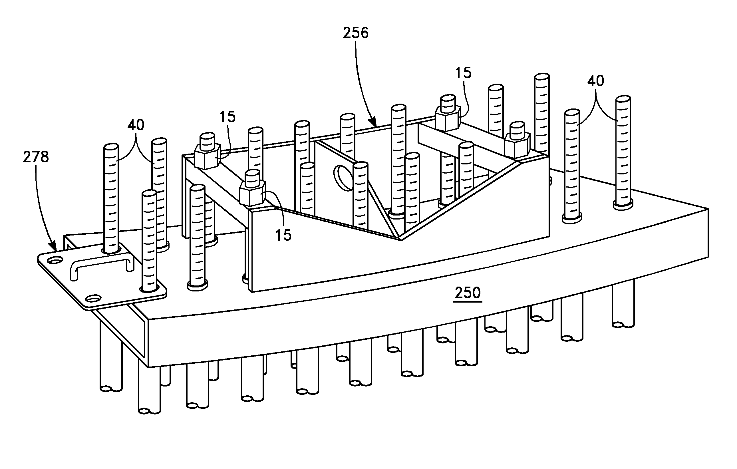
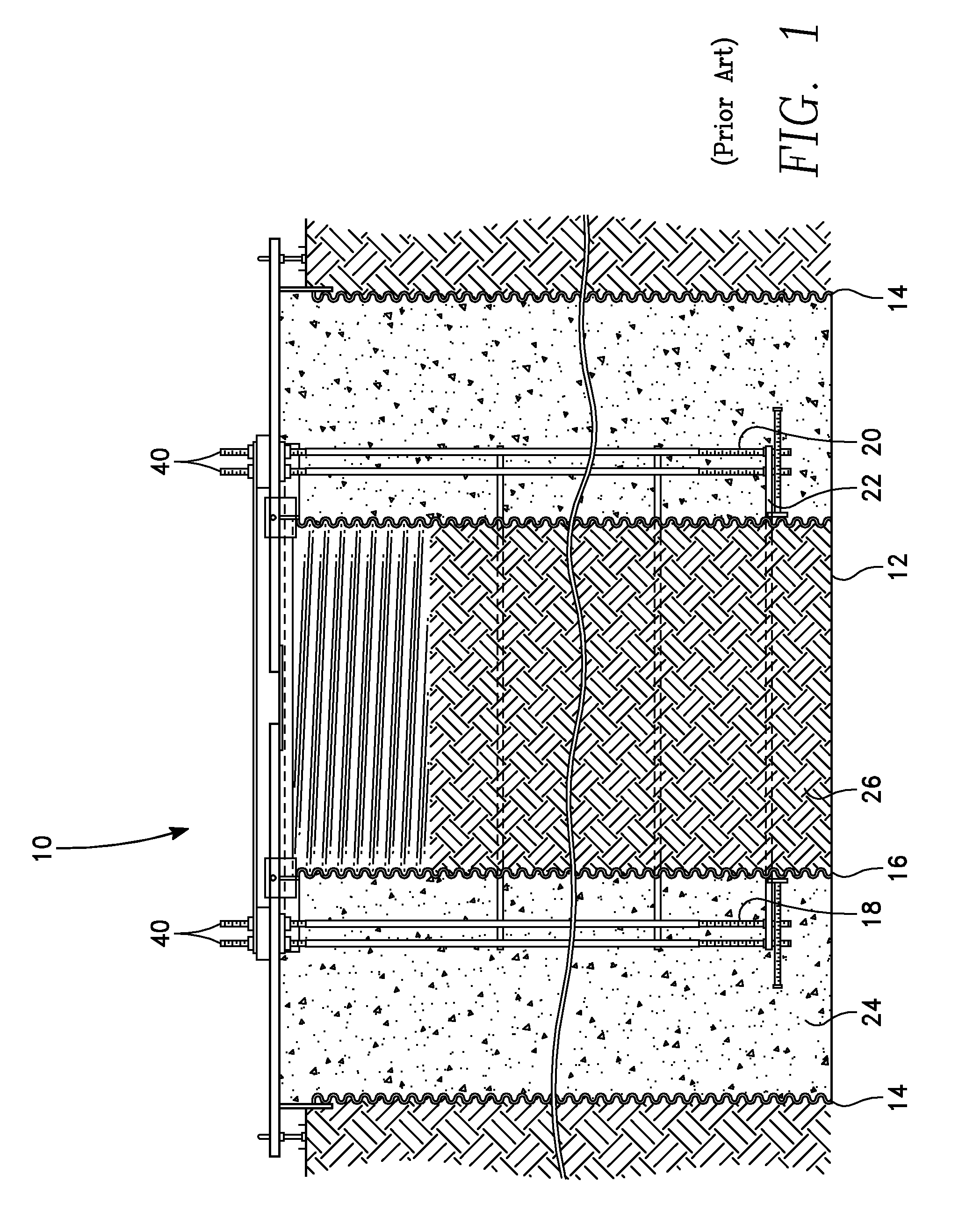
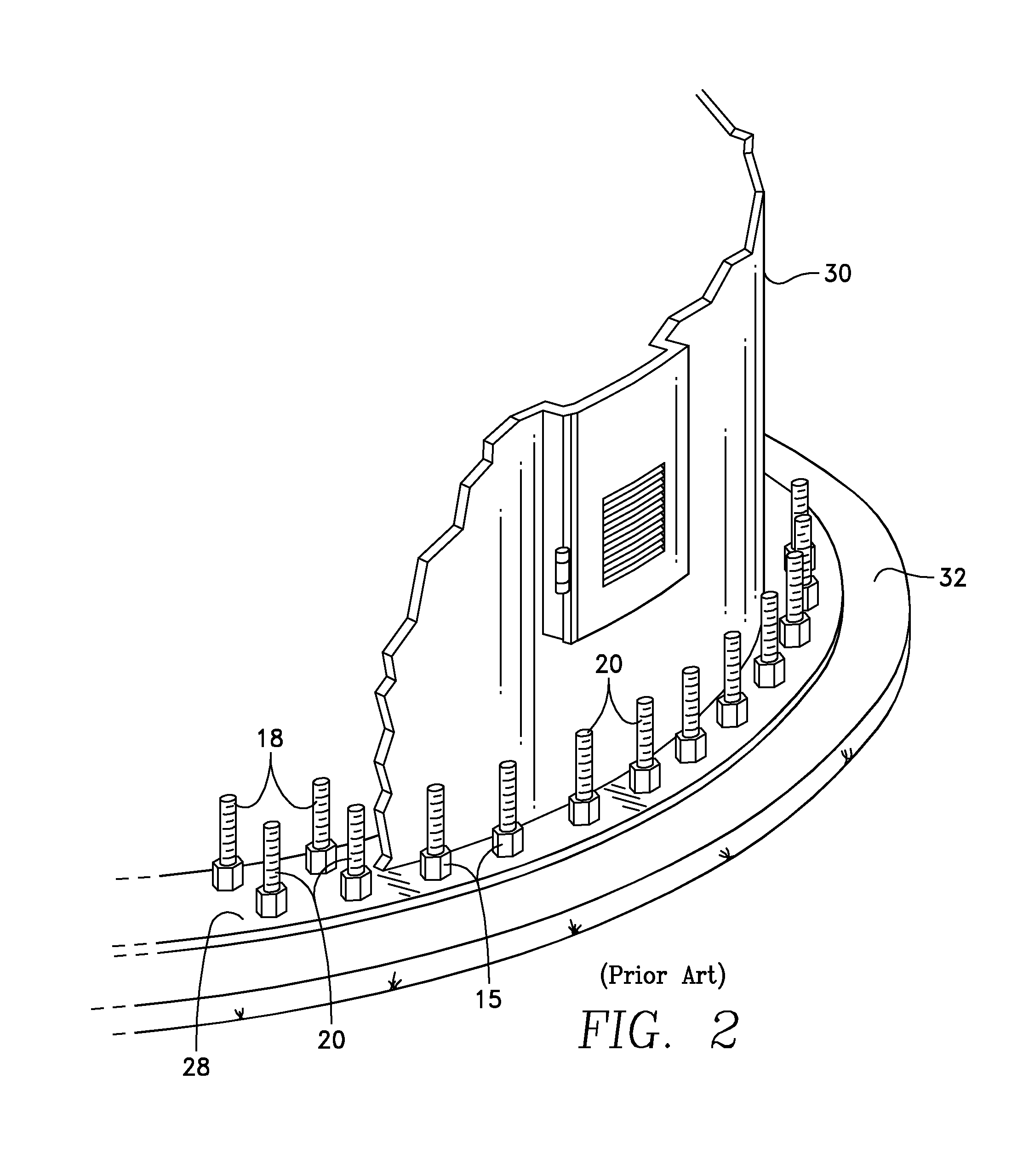
[0043]Referring specifically to the figures, FIG. 1 depicts an embodiment of a known foundation 100 utilized for installation of a relatively tall vertical structure, such as a wind turbine. It is to be appreciated that while the disclosed method and apparatus may be utilized to obtain a foundation 10 such as that depicted in FIG. 1, the procedure for obtaining the foundation is entirely different from the known methods. Foundation 10 comprises a bore hole 12, an outer boundary shell 14 and an inner boundary shell 16, each typically fashioned of corrugated metal pipe (“CMP”), set within the bore hole hole. An inner ring 18 of bolts 40 and an outer ring 20 of bolts 40 are disposed within the annulus formed between the outer boundary shell 14 and the inner boundary shell 16, with the bolts 40 anchored at the lower end of the bore hole 12 to an inbed plate 22. The annulus between the outer boundary shell 14 and the inner boundary shell 16 is filled with concrete 24 and the portion of t...


PUM


Abstract

A method of forming a grout trough for a wind turbine foundation replaces the heavy and single piece template with a plurality of arc-shaped sections which are light weight and connected together to form the grout trough. The individual sections include mechanisms which enable the sections to be removed from the cured concrete by rotation of nuts on the anchor bolts which either pushes or pulls the template section away from the contact with the cured concrete. An embodiment of an individual section has a lifting bale which may be used to pick up an entire bolt package of up to twenty bolts.

Description

CROSS-REFERENCE TO RELATED APPLICATIONS[0001]U.S. Provisional Application No. 61 / 487,670 for this invention was filed on May 18, 2011, for which application this inventor claims domestic priority.BACKGROUND OF THE INVENTION[0002]This invention relates to concrete foundations set within excavations or bore holes which are installed to support wind turbines. More particularly, this invention comprises an apparatus and method for configuring, installing, and setting the anchor bolts for a cylindrical foundation for a wind turbine, and installing a grout trough in the foundation.[0003]U.S. Pat. Nos. 5,586,417 and 5,826,387, both by Henderson, disclose a foundation “which can be poured-on-site monolithically and is of cylindrical construction with many post-tensioned anchor bolts which maintain the poured portion of the foundation under heavy compression, even during periods when the foundation may be subject to high overturning moment.” Henderson's foundation is preferably in the shape ...

Claims


Application Information

Patent Timeline
Patent Type & Authority Patents(United States)
IPC IPC(8): E04G21/18E02D27/42
CPCE02D27/42E04G21/185E02D27/425E04C5/06E04C5/125F03D11/045F03D13/22
Inventor TOOMAN, NORMAN
Owner TOOMAN NORMAN
Why Eureka
Try Eureka