Overhead door with spring-loaded roller hinges

a technology of roller hinges and hinges, which is applied in the direction of hinges, wing accessories, manufacturing tools, etc., can solve the problems of door panels not sealing, door panels that do not provide track brackets with slots or other mechanisms, and dramatically increase heating costs on cold days and cooling costs on hot days

Active Publication Date: 2013-10-15
MORTIER LESTER L
View PDF31 Cites 7 Cited by
  • Summary
  • Abstract
  • Description
  • Claims
  • Application Information

AI Technical Summary

Benefits of technology

[0010]An advantage of the present overhead door with spring-loaded roller hinges is that it allows the door to properly engage the vertical portions of the frame or weather stripping to achieve an effective weather and thermal seal when the door is closed.
[0011]A further advantage of the present spring-loaded roller hinges is that they are readily retrofit to a wide variety of conventional overhead doors. For example, the spring-loaded roller hinges can be readily used in door assemblies with either adjustable or non-adjustable tracks.
[0012]Another advantage of the present overhead door with spring-loaded roller hinges is its adaptability to the varying flange heights of the roller hinges. The slot in the middle dual-hub spring-loaded roller hinges is moved further up the flange then for the lower or shorter dual-hub spring-loaded roller hinge. Similarly, the slot in the upper or taller dual-hub spring-loaded roller hinge is moved still further up the flange then for the middle dual-hub spring-loaded roller hinge. In addition, the springs are easily modified to accommodate the varying slot locations. When torsion springs wrapped around the hinge hub are used, the length of one spring leg is modified to accommodate the varying slot locations. When helical springs are used, the length of the helical spring is slightly longer for the middle hinge than the shorter hinge, and still longer for the taller hinge. The present design avoids the need for more complex and expensive structures to accommodate the varying height of the roller hinges.
[0013]A further advantage of the present overhead door with spring-loaded roller hinges is that it avoids or minimizes binding between the door and its frame. There is a one inch overlap on each side of the door 10 relative to the door jam or frame 7. The panels 11 press directly and flushly against the door jam 11 when the door 10 is closed or is being raised to its open position. No weather stripping is located directly between the door panel 11 and door jam 7. Weather stripping can secured to the perpendicular sides of the door frame to press into or against the door panels 11. The springs allow the door to release from and avoid any binding with the door frame.
[0014]A still further advantage of the present overhead door with spring-loaded roller hinges is that it prevents light, noise, heat, cold, wind, rain, snow, dust, bugs and spiders from getting into the inside of the building.

Problems solved by technology

A problem with conventional overhead doors is that they do allow for this track adjustability toward the top of the vertical section of the track.
In addition, many overhead doors do not provide track brackets with slots or other mechanisms to adjustably align and space the track with the door.
Another problem with conventional overhead doors is that the door panels do not seal against the vertical side sections of the door frame or weather stripping when the door is closed as shown in FIG. 1B.
Unfortunately, when these doors are used in colder or hotter regions, the gaps allow outside air to blow or flow into the interior of the building, which dramatically increases heating costs on cold days, and cooling costs on hot days.
The gaps can also cause unsafe conditions on cold days when ice forms inside near the door even when the door remains closed.
Although weather stripping can help alleviate some gap and air leak problems, these problems frequently persist because the weather stripping can be torn or damaged, is insufficient to close the gap, or looses its resilience over time and on colder days when a good seal is most needed.
A further problem with conventional overhead doors in providing a proper seal between the door and door frame is the varying height of the roller hinges.
The varying flange heights of both the dual-hub and low profile roller hinges complicates the physical structure of conventional mechanisms used to help ensure that the door properly engages the door frame or its weather stripping when closed.
A further problem with conventional overhead door assemblies is that the two lower door panels are joined by a low profile roller hinge that is structurally different than the other roller hinges that join the upper door panels.

Method used


Image

  • Overhead door with spring-loaded roller hinges
  • Overhead door with spring-loaded roller hinges
  • Overhead door with spring-loaded roller hinges

Examples


Embodiment Construction

[0048]While this invention is susceptible of embodiment in many different forms, the drawings show and the specification describes in detail a preferred embodiment of the invention. It should be understood that the drawings and specification are to be considered an exemplification of the principles of the invention. They are not intended to limit the broad aspects of the invention to the embodiment illustrated.

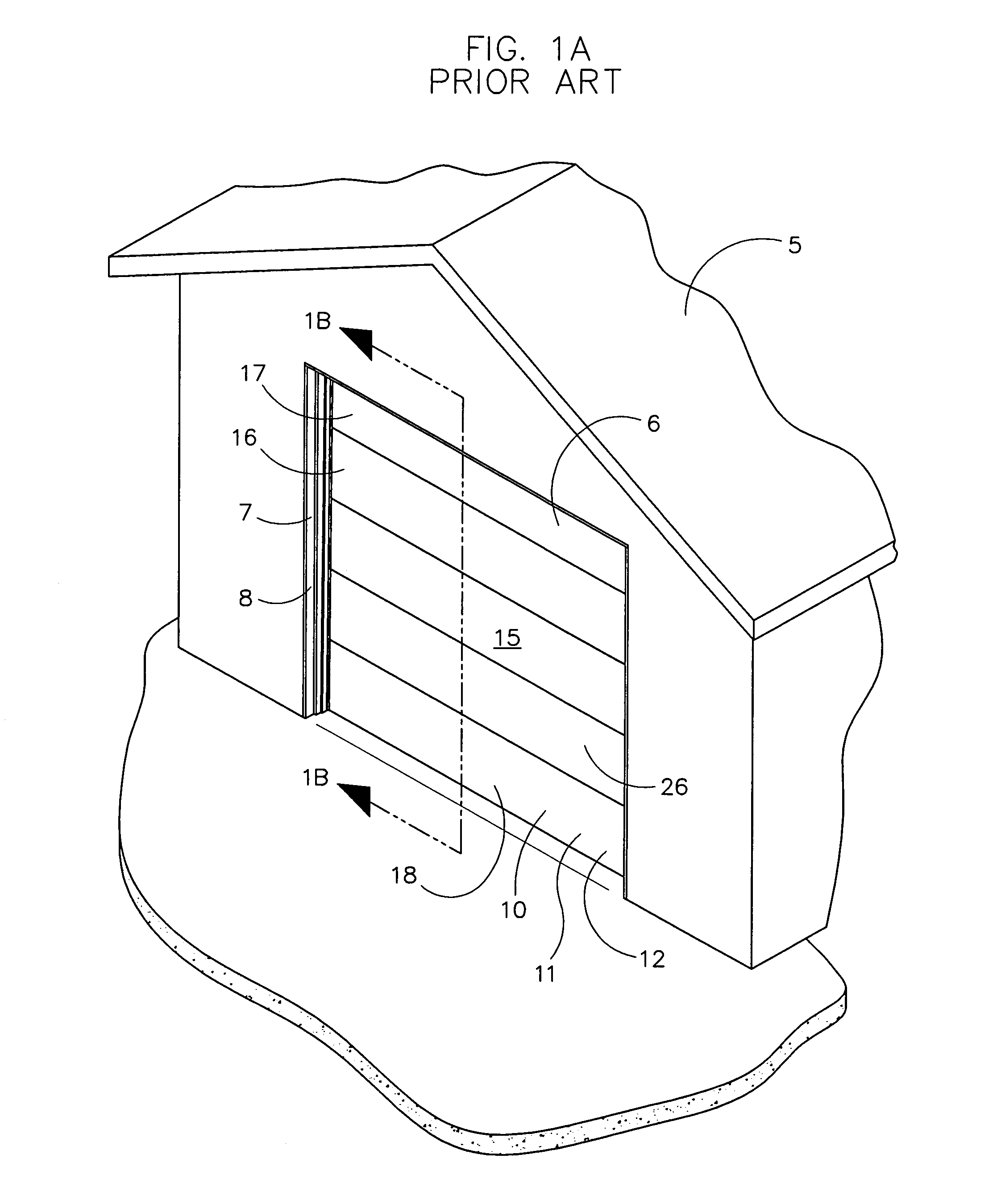
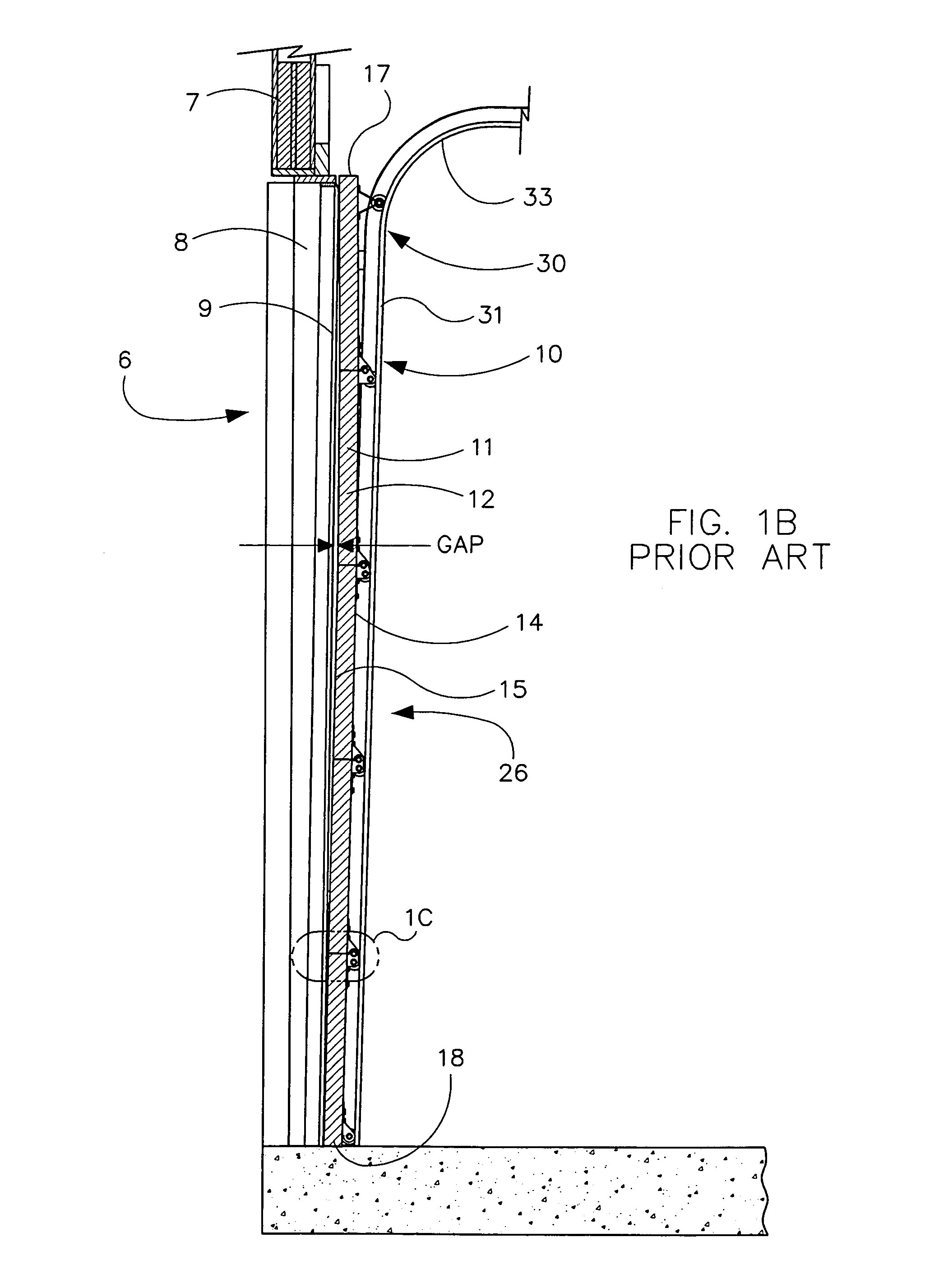
[0049]FIG. 1A shows a building 5 with an opening 6 to access an enclosed interior area. The opening 6 is formed by a frame 7 that includes opposed side framing 8 and top framing. The bottom of the opening 6 is formed by a floor or ground surface. The present invention relates to an overhead door assembly with spring-loaded roller hinges that is generally indicated by reference number 10. The overhead door assembly 10 includes a door 11 formed by several uniformly shaped rectangular panels 12 that extend horizontally from one side 8 of the door frame 7 to the other. When the do...


PUM


Abstract

An overhead door with spring-loaded roller hinges that push the door against its frame or weather stripping to provide an effective weather and thermal seal when the door is closed. The spring-loaded roller hinges are readily retrofit to overhead doors with conventional roller hinges. Each hinge spaces and pivotally secures a roller hub from the base of the hinge. The roller hub is pivotally secured to an inside flange and movably held by an elongated slot in an outer flange. The roller hub supportingly receives the axle of a wheel that rollingly engages a track fixed to the vertical sides of the door frame. Each roller hinge has a spring that biases its roller hub and wheel rearwardly against the fixed track, which pushes the door panels forward and into sealing engagement with the door frame or its weather stripping.

Description

[0001]This application claims priority on U.S. Provisional Application No. 61 / 399,762 filed Jul. 16, 2010; U.S. Provisional Application No. 61 / 459,071 filed Dec. 6, 2010 and U.S. Provisional Application No. 61 / 519,963 filed Jun. 2, 2011.TECHNICAL FIELD OF THE INVENTION[0002]This invention relates to an overhead door with spring-loaded roller hinges to provide a more effective weather and thermal seal when the door is closed.BACKGROUND OF THE INVENTION[0003]Conventional overhead doors include several horizontal panels joined in series to allow the door to move along a track between a lower vertical closed position and a raised horizontal open position. Adjacent panels are pivotally joined by roller hinges that allow the door to move along both the straight and curved sections of the track as shown in FIGS. 1A-1F. Each roller hinge holds a roller wheel that rollingly engages the track. The door is slightly wider than the door frame so that sides of the door extend beyond or overlap th...

Claims


Application Information

Patent Timeline
Patent Type & Authority Patents(United States)
IPC IPC(8): E05D15/00E05D15/06
CPCE05D15/242E05F1/1215E05D7/00E05Y2800/12Y10T16/381Y10T16/5389Y10T16/538E05Y2900/106
Inventor MORTIER, LESTER L.
Owner MORTIER LESTER L
Why Eureka
Try Eureka