Eureka AIR delivers breakthrough ideas for toughest innovation challenges, trusted by R&D personnel around the world.

Illumination lamp

a technology of illumination lamp and circuit module, which is applied in the field of lamps, can solve the problems of reducing the service life of the battery unit, adverse influence of high temperature produced by the circuit module during operation, etc., and achieves the effect of reducing the adverse influence of a high temperature of the circuit modul

Inactive Publication Date: 2013-10-15
LITE ON ELECTRONICS (GUANGZHOU) LTD +1
View PDF4 Cites 36 Cited by
  • Summary
  • Abstract
  • Description
  • Claims
  • Application Information

AI Technical Summary

Benefits of technology

[0007]The object of this invention is to provide an illumination lamp that can reduce effectively an adverse influence of a high temperature of a circuit module on a power supply module.
[0009]Due to the presence of the partitioning unit, thermal convection between the first and second spaces is prevented to reduce adverse influence of a high temperature of the circuit module on the power supply module.

Problems solved by technology

However, in such a lamp structure, since the circuit module is adjacent to the battery unit, a high temperature produced from the circuit module during operation has an adverse influence on the battery unit.
That is, the service life of the battery unit is reduced when the battery unit is in a high temperature environment for a long time period.

Method used


Image

  • Illumination lamp
  • Illumination lamp
  • Illumination lamp

Examples


Embodiment Construction

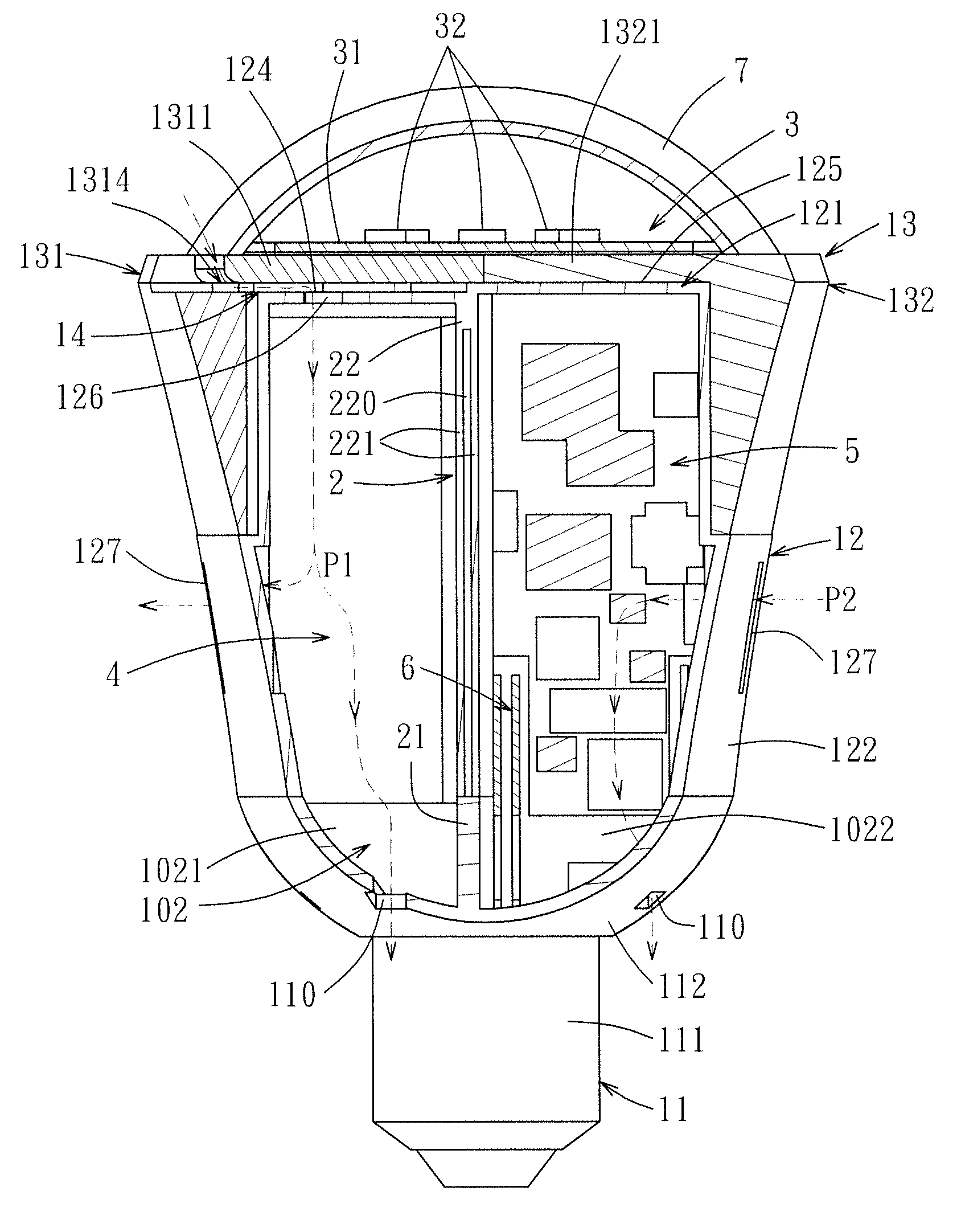
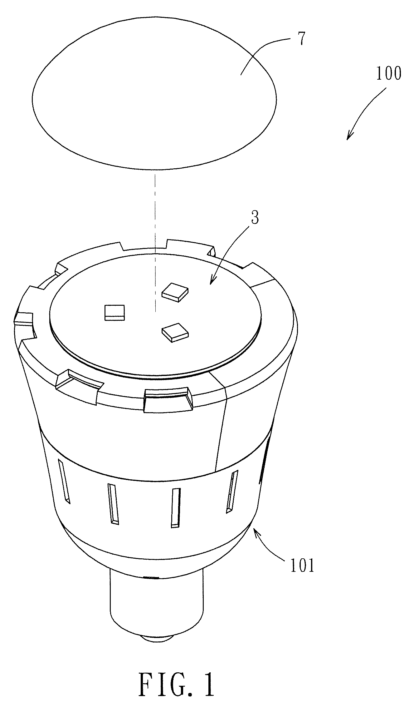
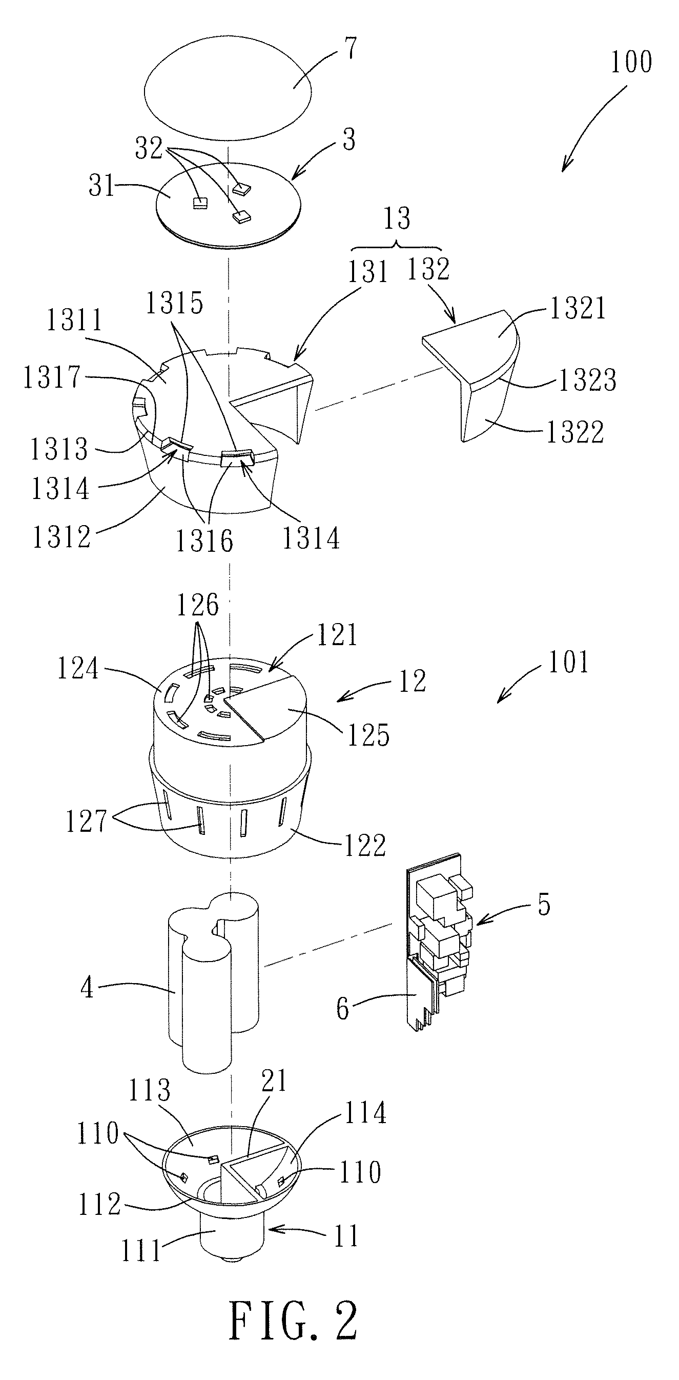
[0018]Referring to FIGS. 1 and 2, the preferred embodiment of an illumination lamp 100 according to this invention includes a lamp body 101, a light-emitting module 3 disposed on the lamp body 101, a power supply module 4, a circuit module 5, a heat-dissipating fin 6, and a cover 7 connected to the lamp body 101 for covering the light-emitting module 3.

[0019]With further reference to FIGS. 3 and 4, the lamp body 101 defines an inner space 102. The partitioning unit 2 is disposed in the lamp body 101 for dividing the inner space 102 into a first space 1021 and a second space 1022 that are not in fluid communication with each other. Preferably, the volume ratio of the first space 1021 to the second space 1022 is 3:1. The power supply module 4 is disposed within the first space 1021. The circuit module 5 is disposed within the second space 1022. In this embodiment, the power supply module is disposed within the first space, but it's not limit thereto. The first space may also be provid...


PUM


Abstract

An illumination lamp comprises a lamp body, a light-emitting module, a power supply module, and a circuit module. The lamp body defines an inner space. The partitioning unit is disposed in the lamp body for dividing the inner space into a first space for receiving the power supply module, and a second space for receiving the circuit module. Due to the presence of the partitioning unit, thermal convection between the first and second spaces is prevented to reduce adverse influence of a high temperature of the circuit module on the power supply module.

Description

CROSS-REFERENCE TO RELATED APPLICATION[0001]This application claims priority of Chinese Application No. 201110051036.9, filed on Mar. 1, 2011.BACKGROUND OF THE INVENTION[0002]1. Field of the Invention[0003]This invention relates to a lamp, and more particularly to an illumination lamp that includes a partitioning unit disposed between a power supply module and a circuit module.[0004]2. Description of the Related Art[0005]A conventional emergency illumination lamp (e.g. disclosed in Taiwanese Utility Model No. M363552) includes a circuit module and a battery unit that are disposed within the same space of a lamp body.[0006]However, in such a lamp structure, since the circuit module is adjacent to the battery unit, a high temperature produced from the circuit module during operation has an adverse influence on the battery unit. That is, the service life of the battery unit is reduced when the battery unit is in a high temperature environment for a long time period.SUMMARY OF THE INVEN...

Claims


Application Information

Patent Timeline
Patent Type & Authority Patents(United States)
IPC IPC(8): F21S4/00F21V21/00
CPCF21V23/009F21K9/1355F21V29/83F21V29/15F21K9/23
Inventor LEE, TSUNG-CHILI, PO-WEIHSU, SHIH-CHANGYU, CHIN-YIN
Owner LITE ON ELECTRONICS (GUANGZHOU) LTD
Why Eureka
Eureka Blog
Learn More