

Disk stacking method and apparatus
a technology stacking methods, which is applied in the manufacture of record carriers, thin material processing, base layer manufacturing, etc., can solve the problems of inside circumferential surfaces (e.g., edges) of disk-shaped glass substrates that are damaged
- Summary
- Abstract
- Description
- Claims
- Application Information
AI Technical Summary
Benefits of technology
Problems solved by technology
Method used
Image

Examples
Embodiment Construction
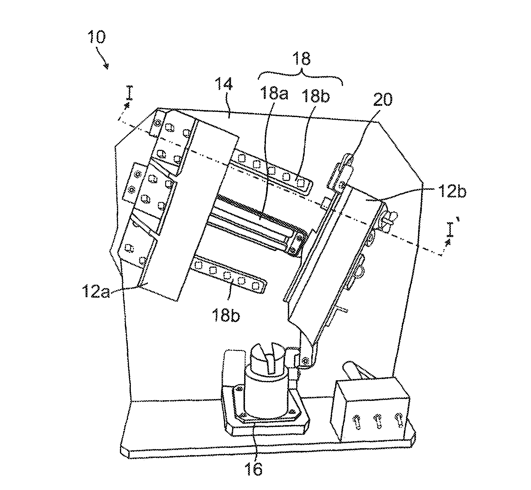
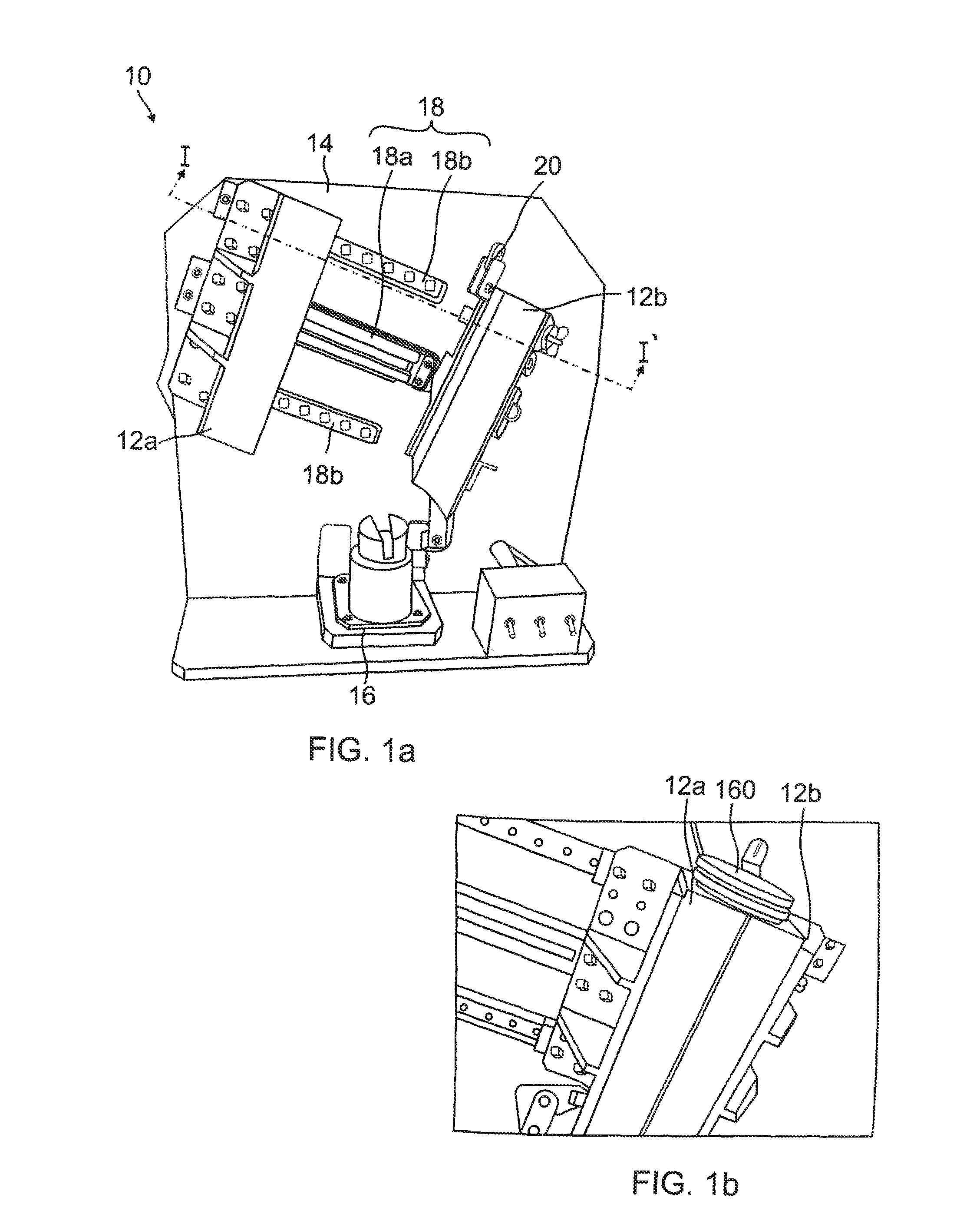
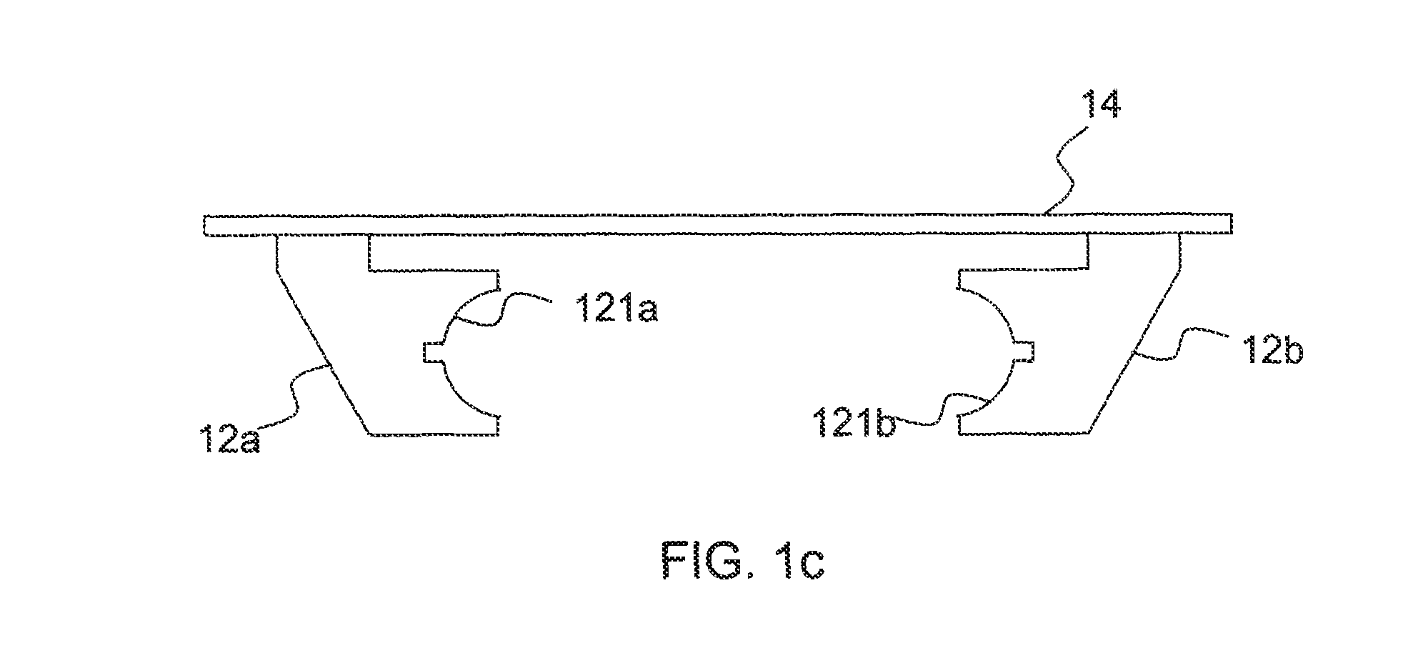
[0037]As the present invention allows for various changes and numerous embodiments, particular embodiments will be illustrated in the drawings and described in detail in the written description. However, this is not intended to limit the present invention to particular modes of practice, and it is to be appreciated that all changes, equivalents, and substitutes that do not depart from the spirit and technical scope of the present invention are encompassed in the present invention.
[0038]The terms used in the present specification are merely used to describe particular embodiments, and are not intended to limit the present invention. An expression used in the singular encompasses the expression of the plural, unless it has a clearly different meaning in the context. In the present specification, it is to be understood that the terms such as “including” or “having,” etc., are intended to indicate the existence of the features, numbers, steps, actions, components, parts, or combinations...
PUM
 Abstract
Description
Claims
Application Information