
Card connector

a card connector and connector technology, applied in the direction of coupling device connection, coupling device two-part connection, coupling/disengagement of coupling parts, etc., can solve the problem of easy short-disconnection between electronic card and electrical terminal, and achieve the effect of avoiding short-disconnection

Inactive Publication Date: 2013-10-15
PROCONN TECH CO LTD
View PDF6 Cites 6 Cited by
  • Summary
  • Abstract
  • Description
  • Claims
  • Application Information

AI Technical Summary

Benefits of technology

The invention described in this patent text allows for a secure and reliable electrical connection between an electronic card and the main circuit board (or contact portion) even during shaking or pulling of the card. This is achieved by using two elastic arms that press down on the electronic card, creating a strong connection that prevents disconnection.

Problems solved by technology

However, when the card connector is shaken or the electronic card is pulled out of the card connector, a short disconnection easily happens between the electronic card and the electrical terminals on account of a poor normal contact force of the elastic portion.

Method used


Image

  • Card connector
  • Card connector
  • Card connector

Examples


Embodiment Construction

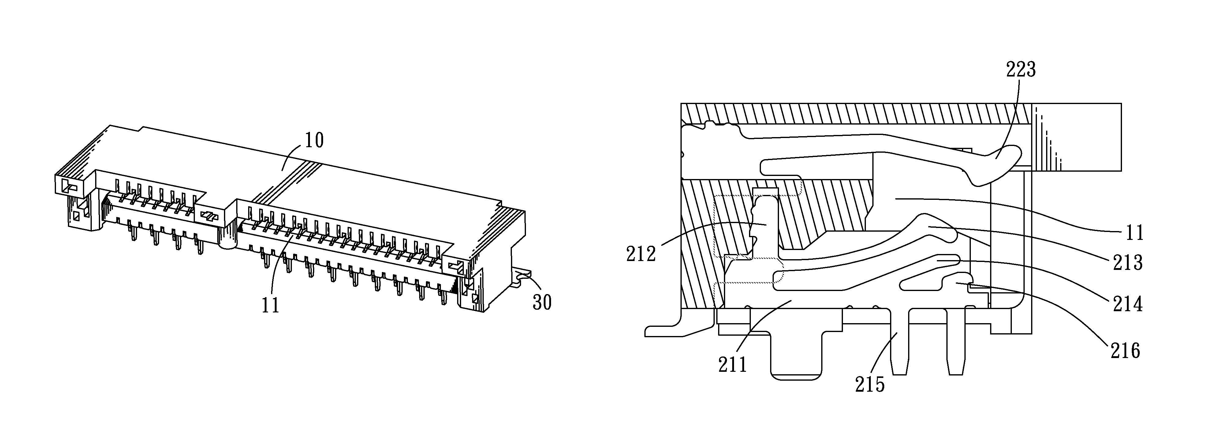
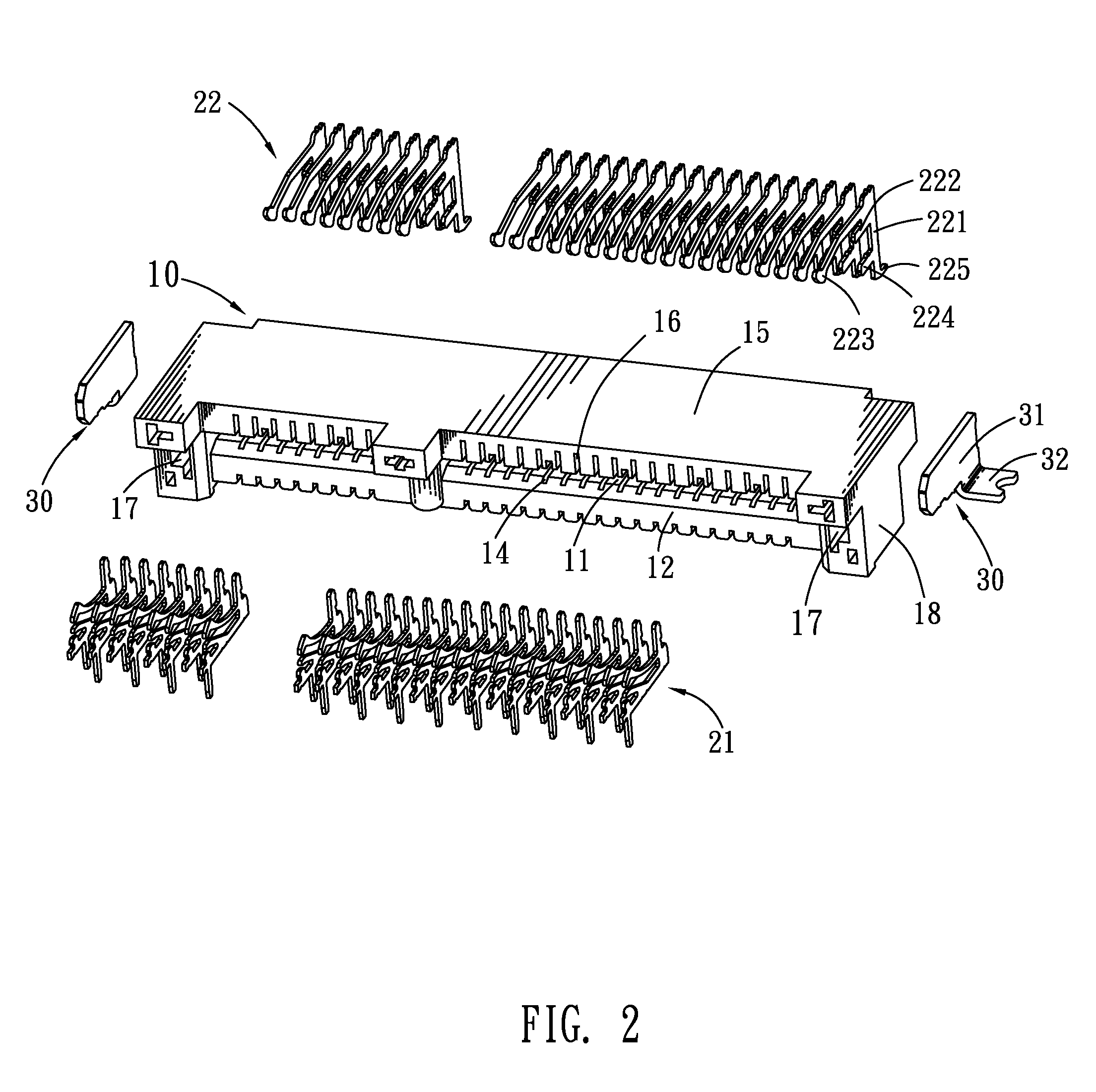
[0013]Referring to FIGS. 1-2, a card connector in accordance with an embodiment of the present invention includes an insulating housing 10, a plurality of first electrical terminals 21 and second electrical terminals 22 mounted in the insulating housing 10, and two fastening members 30 mounted to two opposite ends of the insulating housing 10.

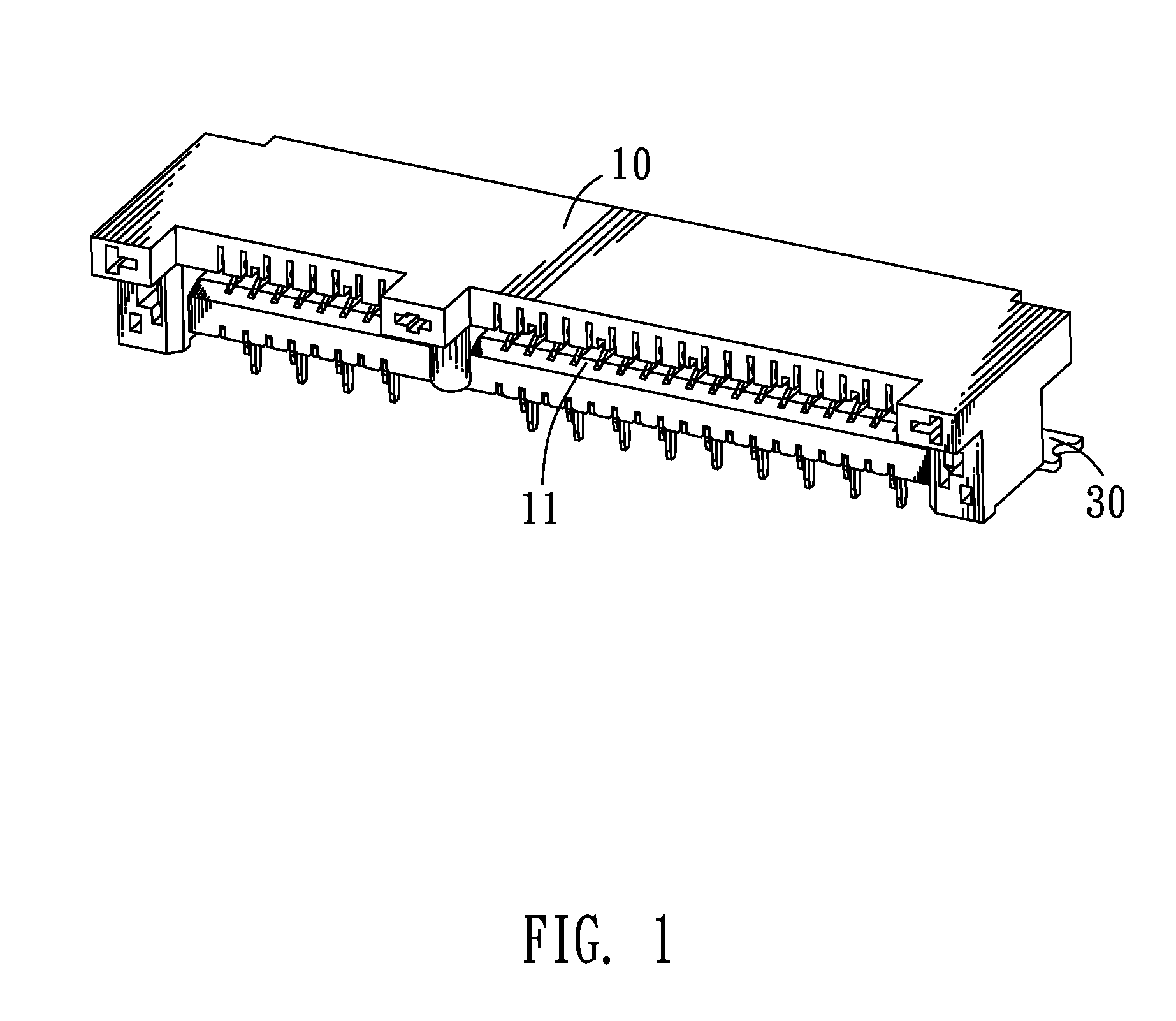
[0014]With reference to FIGS. 2-3, the insulating housing 10 of a long rectangular shape has a front side thereof recessed rearward to form a card recess 11 extending horizontally for receiving an electronic card (not shown). Accordingly, a bottom wall 12, a rear wall 13, a top wall 15 and a pair of side walls 18 are formed around the card recess 11. The bottom wall 12 defines a plurality of first terminal fillisters 14 arranged at regular intervals along a transverse direction thereof. Each first terminal fillister 14 includes a first receiving fillister 141 vertically penetrating through the bottom wall 12 to communicate with the card recess ...


PUM


Abstract

A card connector includes an insulating housing defining a card recess, first electrical terminals and second electrical terminals disposed in the insulating housing. Each first electrical terminal has a base strip, a first fixing arm, a first elastic arm extending forward and inclining upward from the first fixing arm, a second elastic arm slantwise extending forward and upward from a substantial middle of the base strip and apart located under the first elastic arm, and a contact portion protruding upward from a front end of the base strip and apart located under the second elastic arm. A distal end of the first elastic arm elastically stretches upward into the card recess, and can be pressed downward to resist against the second elastic arm so as to make the second elastic arm further contact with the contact portion when an electronic card is inserted into the card recess.

Description

BACKGROUND OF THE INVENTION[0001]1. Field of the Invention[0002]The present invention relates to a card connector, and more particularly to a card connector capable of ensuring a steady connection between electrical terminals thereof and an electronic card.[0003]2. The Related Art[0004]With rapid development of digital technology, a variety of digital electronic products, such as digital cameras and cell phones, have been widely used in our daily life. In order to increase memory space and expand performance of the digital electronic products, the digital electronic products always dispose electronic cards therein. So, various card connectors are widely used in the digital electronic products for receiving the electronic cards therein to realize an electrical connection and an information transmission between the corresponding digital electronic product and the electronic card.[0005]In general, the card connector includes an insulating housing defining a card recess for receiving an...

Claims


Application Information

Patent Timeline
Patent Type & Authority Patents(United States)
IPC IPC(8): H01R24/00
CPCH01R12/721H01R13/2442H01R12/73
Inventor WANG, HUNG-CHIYIN, TE-HUNG
Owner PROCONN TECH CO LTD
Learn More