Control apparatus for vehicular drive system

a control apparatus and vehicular drive technology, applied in the direction of engine controllers, mechanical apparatus, machines/engines, etc., can solve the problems of increasing the number of parts of the vehicle, increasing the cost of manufacture of the vehicle, and causing the rattling noise to be generated, so as to reduce the transmission of the rattling noise, reduce the cost, and reduce the generation. effect of cos

Inactive Publication Date: 2013-10-15
TOYOTA JIDOSHA KK
View PDF7 Cites 6 Cited by
  • Summary
  • Abstract
  • Description
  • Claims
  • Application Information

AI Technical Summary

Benefits of technology

[0007]In the second aspect of the invention, (1) the above-described first drive wheel and the above-described second drive wheel are front and rear drive wheels driven by the above-described engine through a center differential gear device, and (2) the above-described differential limiting device is provided in the above-described center differential gear device, to limit a differential rotary motion between the above-described front and rear drive wheels.
[0008]In the third aspect of the invention, (1) the above-described first drive wheel and the above-descried second drive wheel are a pair of right and left drive wheels driven by the above-described engine through a differential gear device, and (2) wherein the above-described differential limiting device is provided in the above-described differential gear device, to limit a differential rotary motion between the above-described pair of right and left drive wheels.
[0009]In the fourth aspect of the invention, the above-described on-engine-starting differential limiting means limits the differential rotary motion between the above-described first drive wheel and the above-described second drive wheel, on the basis of a drive torque varying due to starting of the above-described engine under the control of the above-described automatic engine starting control means, and according to a stored predetermined relationship.
[0010]The vehicular drive system control apparatus according to the first aspect of the invention comprises the on-engine-starting differential limiting means for commanding the above-described differential limiting device to limit the differential rotary motion between the above-described first drive wheel and the above-described second drive wheel, upon automatic starting of the above-described engine under the control of the above-described automatic engine starting control means. Accordingly, the limitation of the differential rotary motion between the first drive wheel and the second drive wheel by the above-described differential limiting device ensures the starting of the engine without a backlash which exists in the power transmitting path between the engine and the first and second drive wheels due to a circulating torque generated due to a small amount of difference between the diameters of the first and second drive wheels, thereby permitting economical and easy reduction of generation of an abnormal sound upon starting of the engine in a running state of the vehicle, that is, a rattling noise due to the above-indicated backlash. The present control apparatus eliminates a need for providing sound muffler members between the vehicular drive system and vehicular compartments, for example, for reducing the transmission of the rattling noise from the vehicular drive system to the vehicular compartments, and prevents an increase of the number of parts of the vehicle and an increase of costs due to the increase of the number of these parts which would be caused by the provision of those sound muffler members. Further, the present control apparatus does not require a difficult control of an electric motor of the vehicular drive system so as to reduce an amount of variation of a vehicle drive torque upon the starting of the engine, for preventing the generation of the above-indicated rattling noise.
[0006]The object of the first aspect of the invention is achieved according to the present invention, which provides (1) a control apparatus for a drive system of a vehicle provided with a first drive wheel and a second drive wheel each of which is rotated by an output of an engine transmitted thereto, and a differential limiting device configured to limit a differential rotary motion between the above-described first drive wheel and the above-described second drive wheel, the control apparatus being provided with automatic engine starting determining means for determining whether a predetermined automatic engine starting condition is satisfied while the above-described engine is at rest in a running state of the vehicle, and automatic engine starting control means for automatically starting the above-described engine when it is determined that the above-described automatic engine starting condition is satisfied, (2) the control apparatus being characterized by comprising on-engine-starting differential limiting means for commanding the above-described differential limiting device to limit the differential rotary motion between the above-described first drive wheel and the above-described second drive wheel, upon automatic starting of the above-described engine under the control of said automatic engine starting control means.
[0012]In the vehicular drive system control apparatus according to the third aspect of the invention, the above-described first drive wheel and the above-described second drive wheel are a pair of right and left drive wheels driven by the above-described engine through a differential gear device, and the above-described differential limiting device is provided in the above-described differential gear device, to limit a differential rotary motion between the above-described pair of right and left drive wheels. In this case, the limitation of the differential rotary motion between the pair of right and left drive wheels by the differential limiting device ensures the starting of the engine in the running state of the vehicle without the backlash in the power transmitting path between the engine and the pair of right and left drive wheels, thereby permitting economical and easy reduction of generation of the abnormal sound upon starting of the engine in the running state of the vehicle, even where the vehicle is a front-drive vehicle or a rear-drive vehicle.
[0006]The object of the first aspect of the invention is achieved according to the present invention, which provides (1) a control apparatus for a drive system of a vehicle provided with a first drive wheel and a second drive wheel each of which is rotated by an output of an engine transmitted thereto, and a differential limiting device configured to limit a differential rotary motion between the above-described first drive wheel and the above-described second drive wheel, the control apparatus being provided with automatic engine starting determining means for determining whether a predetermined automatic engine starting condition is satisfied while the above-described engine is at rest in a running state of the vehicle, and automatic engine starting control means for automatically starting the above-described engine when it is determined that the above-described automatic engine starting condition is satisfied, (2) the control apparatus being characterized by comprising on-engine-starting differential limiting means for commanding the above-described differential limiting device to limit the differential rotary motion between the above-described first drive wheel and the above-described second drive wheel, upon automatic starting of the above-described engine under the control of said automatic engine starting control means.

Problems solved by technology

Upon this automatic starting of the engine, which causes a comparatively large drive torque to be transmitted to a power transmitting path between the engine and the first and second drive wheels, an abnormal sound so-called a “rattling noise” is generated due to a backlash existing in the power transmitting path.
However, the above-described solutions are disadvantageous in that the provision of the above-described sound muffler members increases the number of parts of the vehicle and the cost of manufacture of the vehicle, and the above-indicated control of the electric motor is difficult and does not permit complete elimination of generation of the rattling noise.

Method used


Image

  • Control apparatus for vehicular drive system
  • Control apparatus for vehicular drive system
  • Control apparatus for vehicular drive system

Examples


embodiment 1

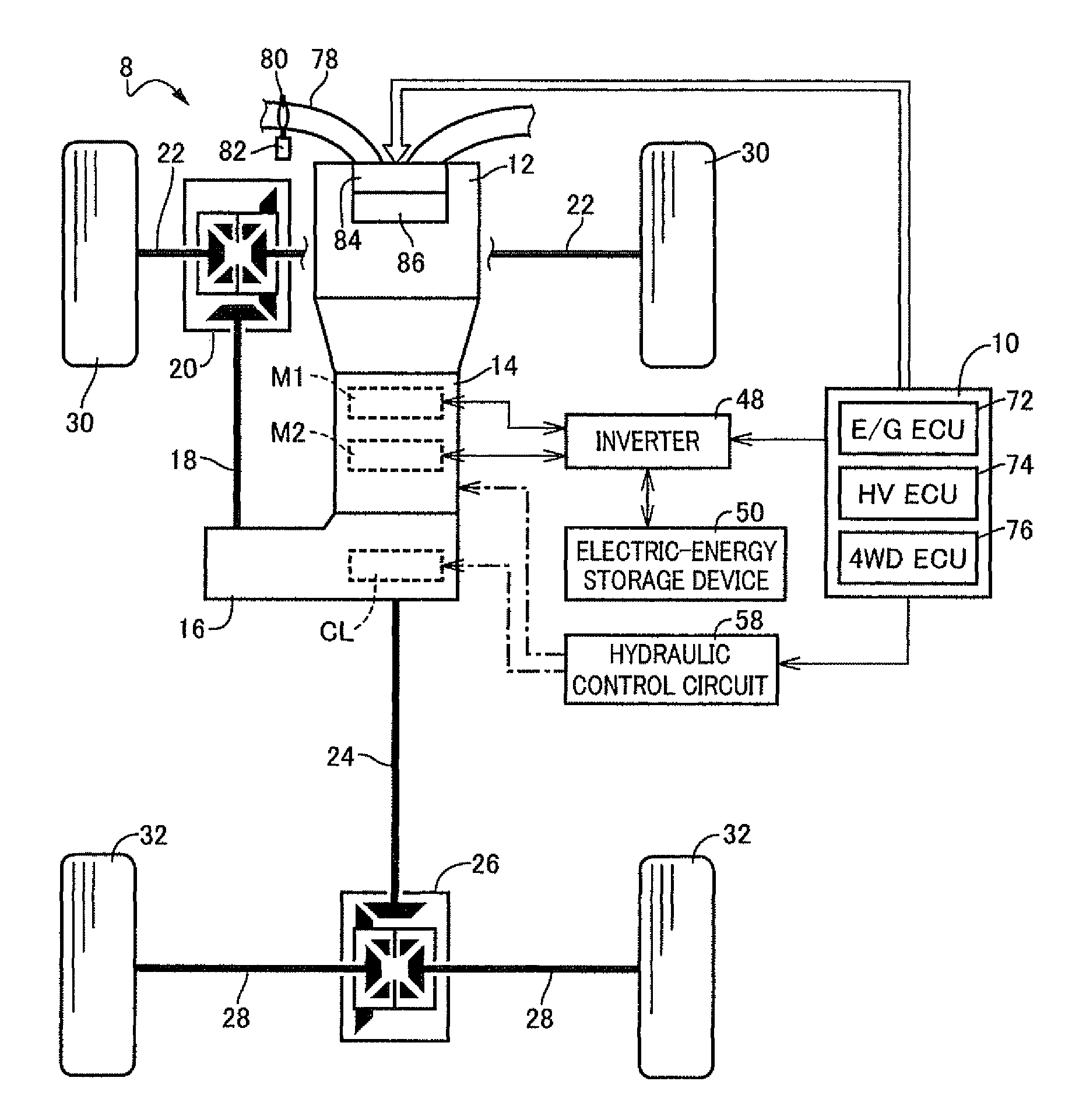
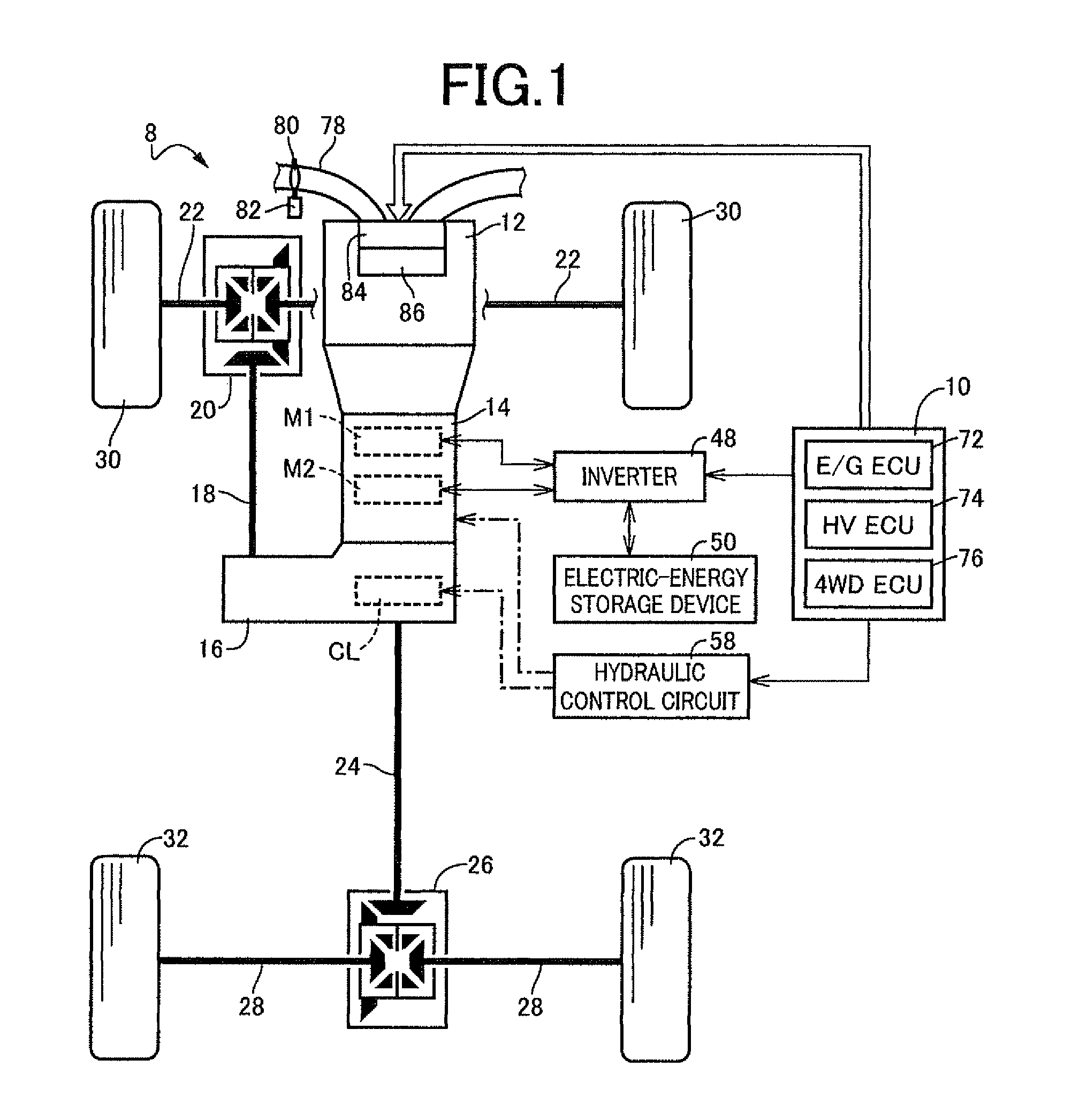
[0023]FIG. 1 is the view for explaining a vehicular drive system 8, and an electronic control device 10 functioning as a control apparatus for the vehicular drive system 8, which is configured according to one embodiment of this invention. This vehicular drive system 8 is suitably used for a hybrid vehicle of a front and rear drive type (four-wheel-drive type), which is basically designed as a front-engine rear-drive (FR) vehicle. As shown in FIG. 1, the vehicular drive system 8 is provided with an engine 12, a power transmitting device 14, a transfer device 16, a front propeller shaft 18, a front wheel differential gear device (front differential) 20, a pair of right and left front wheel axles 22, a rear propeller shaft 24, a rear wheel differential gear device (rear differential) 26, and a pair of right and left rear wheel axles 28. The above-described engine 12, which functions as a drive force source for running, is an internal combustion engine such as a gasoline engine or a di...

embodiment 2

[0054]Another embodiment of this invention will be described next. In the embodiment described below, the same reference signs will be used to identify the elements that are identical with those in the preceding embodiment, and the description of these elements is omitted.

[0055]FIG. 7 is the view for explaining an arrangement of the vehicular drive system 8 according to another embodiment of the present invention. As shown in FIG. 7, the transfer device 16 in this embodiment is provided with: the power transmitting device 62 having the drive gear 66 connected to the output shaft 44, the driven gear 68 connected to the front propeller shaft 18, and the transmission belt 70 connecting the drive gear 66 and the driven gear 68, for transmitting the drive force from the output shaft 44 to the front propeller shaft 18; and the differential limiting clutch CL for selectively connecting the output shaft 44 integrally connected to the rear propeller shaft 24, to the drive gear 66 of the powe...

embodiment 3

[0057]FIG. 8 is the view for explaining an arrangement of the vehicular drive system 8 according to a further embodiment of this invention. The vehicular drive system 8 according to the present embodiment is suitably used for a rear-wheel-drive (FR) vehicle having a pair of right and left rear drive wheels 32, and is not provided with the transfer device 16 provided in the embodiment 1. The rear wheel differential gear device 26 is provided with the differential limiting clutch (differential limiting device) CL configured to connect a differential casing 98 selectively to one of the rear wheel axles 28. The above-described differential limiting clutch CL limits the differential rotary motion between the right and left rear drive wheels 32. In this rear wheel differential gear device 26, the differential limiting torque TL is controlled by controlling the hydraulic pressure of the hydraulic actuator of the differential limiting clutch CL so as to obtain the desired differential limit...


PUM


Abstract

Providing a control apparatus for a vehicular drive system, which permits economical and easy reduction of generation of an abnormal sound upon starting of an engine in a running state of a vehicle. The control apparatus includes on-engine-starting differential limiting means for commanding a differential limiting clutch to limit differential rotary motion between front and rear drive wheels, in advance of automatic starting of an engine under the control of automatic engine starting control means. Accordingly, the limitation of the differential rotary motion between the front and the rear drive wheels by the differential limiting clutch ensures the starting of the engine without backlash which exists in the power transmitting path between the engine and the front and rear drive wheels, thereby permitting economical and easy reduction of generation of the abnormal sound upon starting of the engine in a running state of the vehicle.

Description

TECHNICAL FIELD[0001]The present invention relates to a control apparatus for a vehicular drive system, which is configured to reduce generation of an abnormal sound upon starting of an engine in a running state of a vehicle.BACKGROUND ART[0002]There is known a vehicular drive system having first drive wheels and second drive wheels which are driven by an output of an engine transmitted thereto, and a differential limiting device constructed to limit a differential rotary motion between the first and second drive wheels. Patent Document 1 shows an example of such a vehicular drive system. This Patent Document 1 discloses a four-drive-wheel hybrid vehicle wherein an output of a drive power source having an engine and electric motors is distributed through a transfer device to front drive wheels and rear drive wheels.PRIOR ART DOCUMENT[0003]Patent Document 1: JP-2005-29063 ASUMMARY OF THE INVENTIONObject Achieved by the Invention[0004]In the conventional vehicular drive system describ...

Claims


Application Information

Patent Timeline
Patent Type & Authority Patents(United States)
IPC IPC(8): B60W10/04
CPCB60W10/16B60W30/192B60W10/06B60W10/14F02D29/02Y10T477/688
Inventor OBA, MITSURU
Owner TOYOTA JIDOSHA KK
Why Eureka
Try Eureka