
Methods and devices for intradermal injection

a technology of intradermal injection and device, which is applied in the direction of intravenous devices, infusion needles, other medical devices, etc., can solve the problems of intradermal injection failure, difficult intradermal injection, and loss of delivered compound on the surface of the skin, so as to facilitate intradermal injection and minimize user skill , the effect of minimal training

Active Publication Date: 2013-10-15
SID TECH LLC +1
View PDF47 Cites 27 Cited by
  • Summary
  • Abstract
  • Description
  • Claims
  • Application Information

AI Technical Summary

Benefits of technology

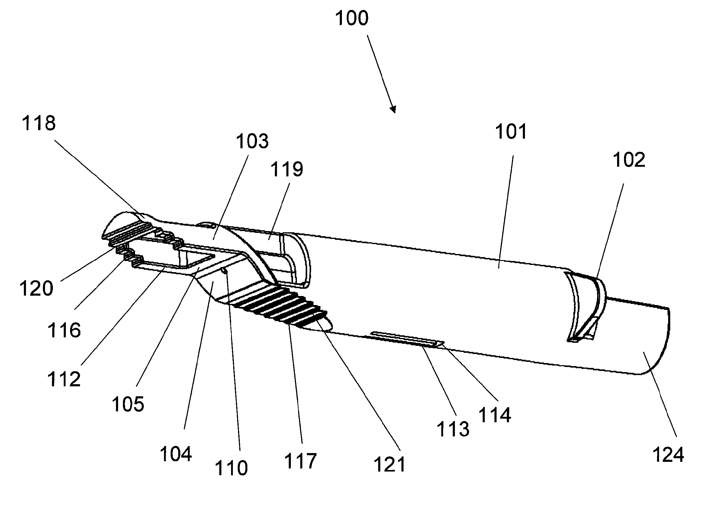
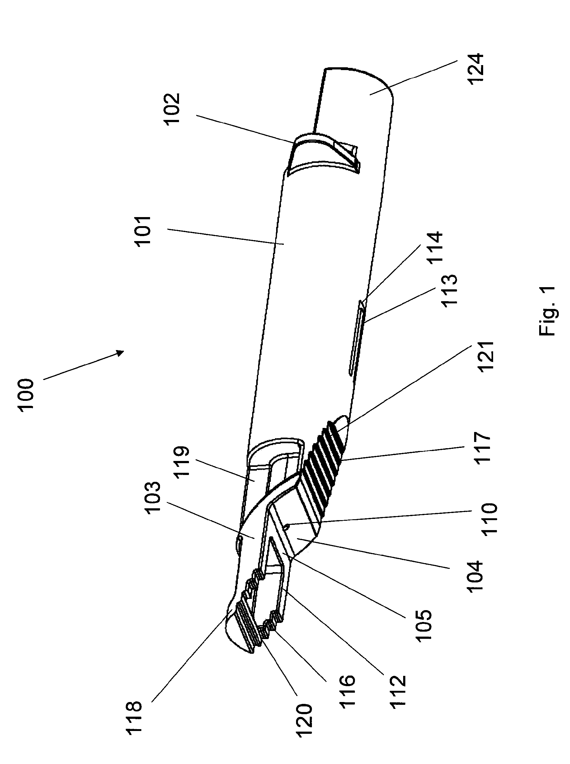
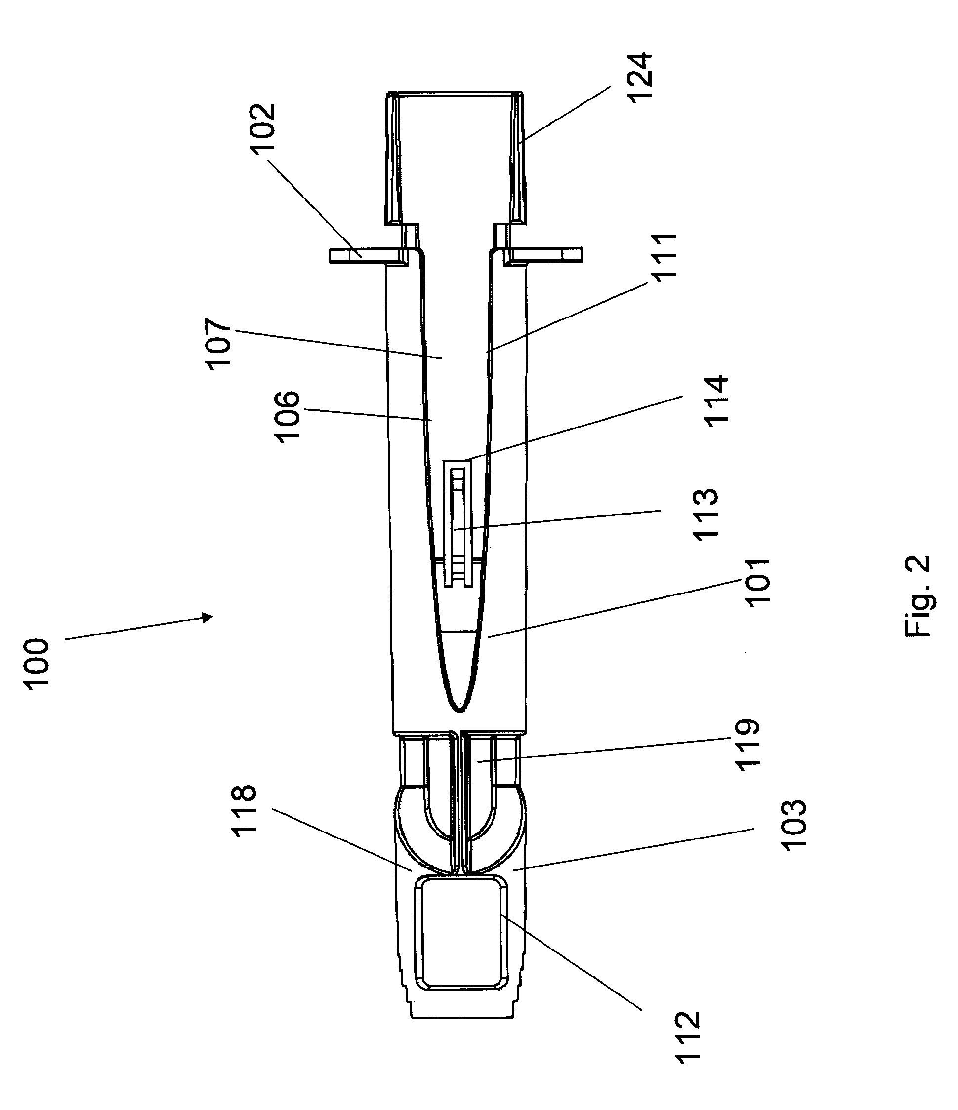
[0010]The present invention relates to devices and methods for the administration of compositions into the intradermal layer of the skin. An adapter device is provided, according to one aspect of the present invention, that facilitates intradermal delivery and can be used with minimal training Specifically, the adapter device minimizes the user skill required for correct insertion of the needle and accurate administration of an intradermal dosage.
[0011]In one embodiment, the adapter device of the present invention is intended for use with a conventional drug delivery system, such as a syringe, with the adapter and the syringe being arranged in a sliding relationship. Alternatively, a needle assembly may be provided integrally with the adapter device, eliminating the need for a needle integral with a syringe. In one embodiment of the adapter device, the user is able to observe the drug injection process. After the injection is completed, the user removes and discards the syringe and the adapter. In some embodiments, the user shields the needle by placing the adapter in a discard position following injection.
[0012]Adapter devices and needle assemblies of the present invention have surfaces that contact and deform the skin to provide an injection site at which the needle cannula can be inserted and then extended generally parallel to, but below, the surface of the skin. Adapter devices generally have first and second primary skin contacting surfaces provided on generally different, adjacent planes and positioned at an angle of less than 180° relative to each other, which act to deform a target tissue site when the adapter is applied to the skin. In use, the skin conforms to the first and second primary skin contacting surfaces of the adapter, and the needle cannula penetrates through the epidermis and dermis at a shallow angle to the surface of the skin, for example at an angle of 10° to 70°, preferably 15° to 6°. The cannula is further extended into the dermis along a path generally parallel to the second primary skin contacting surface for a distance, and the injectite is deposited in the dermal layer at a distance from the cannula penetration site. The adapter may include a first secondary skin contacting surface positioned proximal to the first primary skin contacting surface and / or a second secondary skin contacting surface positioned distal to the second primary skin contacting surface which act to limit tissue distortion.
[0013]The arrangement and configuration of the first and second primary skin contacting surfaces, and the angle at which the needle cannula exits the adapter device, facilitate extension of the cannula into the dermal layer at a depth, and for a distance, that allows deposition of the injected compound in the dermis and far enough away from the cannula penetration site to prevent loss of the injected composition. The structure of the adapter device provides a path for the cannula to enter the skin at a shallow angle to the surface of the skin, ensuring that the composition is delivered to the dermal layer rather than subcutaneously, and also limits the distance the cannula travels, ensuring that the composition is deposited in the dermal layer at an appropriate distance from the injection site.
[0015]The positioning of the cannula tip in the dermis, and the length of the cannula extending into the dermis is controlled by the design and manufacture of the adapter. The cannula length in the dermis is selected to facilitate delivery to the dermis and to minimize the back flow and is generally set in the 0.25 mm to 8 mm range and, in some embodiments, the depth of the cannula orifice in the dermis may be as shallow as 0.25 mm or as deep as 3.00 mm. A shallow positioning is further facilitated by the opportunity to use fine gauge needles. The use of fine gauge cannulas is possible because minimal deflection forces act on the cannula during insertion and is also facilitated by the conventional lancet geometry minimizing the forces acting on the cannula and cannula deflection.

Problems solved by technology

Making intradermal injections is difficult and generally requires an experienced nurse or medical professional.
Incorrect placement of the tip of the needle cannula leads to a failed injection.
Incorrect placement of the needle cannula may also puncture the skin again after being inserted into dermis, with the delivered compound being lost on the surface of the skin.
The insertion of the needle at an incorrect angle and / or depth results in a failed intradermal injection.
Intradermal (ID) injection has been considered for immunization in the past, but has generally been rejected in favor of more reliable intramuscular or subcutaneous routes of administration because of the difficulty in making a successful ID injection.
The technique is known to be quite difficult to perform and requires specialized training A degree of imprecision in the placement of the injection results in a significant number of false negative test results.
As a result, the Mantoux approach has not led to the use of intradermal injection for systemic administration of substances, despite the advantage of requiring smaller doses of substances.
These devices employ complex constructions that tension the skin by vacuum, expanding the mounting surface prior to the needle insertion.
The main limitation of the systems developed by Alchas et al. is the broad range of deposit depth due to assembly tolerances, needle bevel and the variations in skin properties.
The jet effect further limits the performance when a shallow delivery is attempted.
The lack of suitable devices to accomplish reproducible delivery to the epidermal and dermal skin layers has limited the widespread use of the ID delivery route.
Using conventional devices, ID injection is difficult to perform, unreliable and painful to the subject.

Method used


Image

  • Methods and devices for intradermal injection
  • Methods and devices for intradermal injection
  • Methods and devices for intradermal injection

Examples


example 1

[0121]An ID adapter evaluation was conducted with a machined adapter prototype and a single use syringe. The adapter prototype was sized to accommodate in a sliding relationship BD PLASTIPAK syringe with 1 ml volume, 0.5″ long needle and cannula gage 28. The cannula lancet had a conventional subcutaneous bevel. The injection procedure was as follows: 0.1 or 0.5 ml WFI was aspirated into the syringe; the syringe was placed in the adapter with the needle tip positioned in the cannula passageway; the adapter was applied to the desired injection site; the needle was inserted into dermis; the contents were injected; and the needle was withdrawn and the syringe discarded. The needle placement depth was adjusted to locate the cannula center line at about 0.5 mm from the dermis surface. The needle cannula length in the dermis was set at 4.5 mm. WFI volumes of 50 μl and 100 μl were tested.

[0122]The initial evaluation in volunteers with the injection of 0.1 ml of WFI produced blebs customaril...


PUM


Abstract

Devices and methods for intradermal (ID) administration of diagnostic and therapeutic agents, vaccines and other compounds into the dermal layer of the skin are disclosed. The devices and the methods simplify the ID injection process and increase the consistency of the placement of the needle tip in the dermal space close to the skin surface allowing for a shallow cannula placement in the dermis. Furthermore, the devices and methods broaden the number of sites suitable for ID injection and make the ID injection possible with limited training.

Description

CROSS-REFERENCE TO RELATED APPLICATION[0001]This application is a section 371 of International Application No. PCT / US2008 / 061331, filed Apr. 23, 2008, which was published in the English language on Oct. 30, 2008 under International Publication No. WO 2008 / 131440 A1, which claims the benefit of U.S. Provisional Patent Application No. 60 / 925,609, filed Apr. 23, 2007 and U.S. Provisional Patent Application No. 60 / 928,423, filed May 10, 2007, the disclosure of which is incorporated herein by reference.FIELD OF THE INVENTION[0002]The present invention relates to methods and devices for intradermal injection of drugs, vaccines and other compositions. Specifically, adapter devices and needle assemblies are described that are attachable to, or form a part of, a drug delivery system such as a syringe to facilitate intradermal injection.BACKGROUND[0003]Intradermal injections are used for delivering a variety of diagnostic and treatment compositions into a patient. Substances may be injected i...

Claims


Application Information

Patent Timeline
Patent Type & Authority Patents(United States)
IPC IPC(8): A61M5/00
CPCA61M5/3243A61M5/46A61M5/3287A61M5/3271A61M5/425A61M2005/3247
Inventor TSALS, IZRAIL
Owner SID TECH LLC
Learn More