Ocular positioning droplet dispensing device with a recessed dispensing orifice

a droplet and orifice technology, applied in the field of eye drop dispensers, can solve the problems of inconvenient dispensing orifice, contamination of the dropper nozzle by inadvertent contact, and bottle flexibility with a tapered dropper not providing the optimal means for administering drops into the ey

Active Publication Date: 2008-02-05
BARBER RORY
View PDF17 Cites 27 Cited by
  • Summary
  • Abstract
  • Description
  • Claims
  • Application Information

AI Technical Summary

Benefits of technology

[0006]The present invention employs a recessed dispensing orifice to prevent the inadvertent contact of the dispensing orifice with septic surface that may clog the dispensing orifice or contaminate the medication in the eye drop bottle. Another object of the present invention is to provide an ocular positioning droplet dispensing device of the character described which will be handled and positioned by only one hand of the user leaving the other hand free to assist in holding open the eye being treated.
[0007]Another further object of the present invention is to provide an ocular positioning droplet dispensing device of the character above with minimal training or experience can be quickly and easily positioned over the eye to be treated and with ease and facility be rotated from one eye to the other.

Problems solved by technology

It has been recognized that a flexible bottle with a tapered dropper does not provide optimum means for administering drops into the eye.
A significant problem with previous dispensing devices used for dispensing ophthalmic solutions is contamination of the dropper nozzle by inadvertent contact with septic surfaces such as fingertips and facial surfaces.
This contact also can clog the dispensing orifice making it impossible to dispense further drops.
Contamination of the dispensing orifice can then result in microbial contamination of the solution remaining in the dropper bottle and the transfer of this contamination to either or both eyes.
Since the eye drops may be used several times a day and over long periods of time, it is often necessary to carry the dispenser in a purse or a pocket, the size and configuration of the ocular positioning droplet dispensing device of U.S. Pat. No. 3,934,590 would make carriage in a purse or pocket difficult.

Method used


Image

  • Ocular positioning droplet dispensing device with a recessed dispensing orifice
  • Ocular positioning droplet dispensing device with a recessed dispensing orifice
  • Ocular positioning droplet dispensing device with a recessed dispensing orifice

Examples


Embodiment Construction

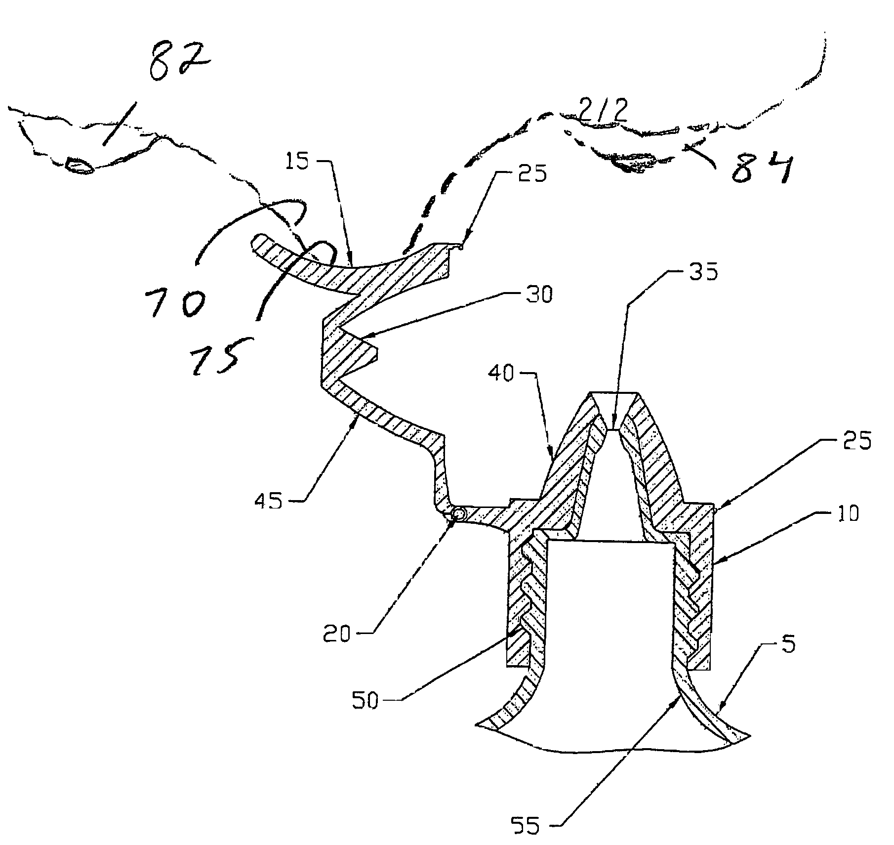
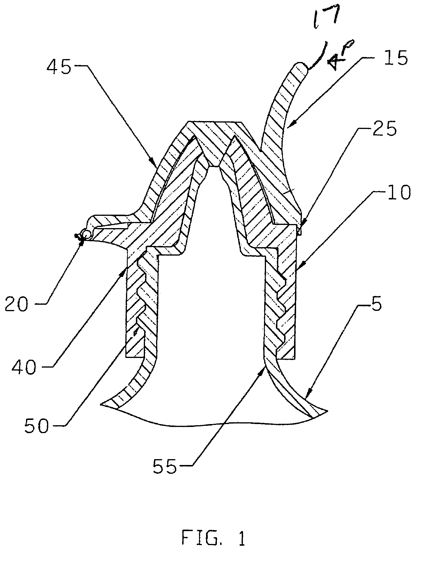
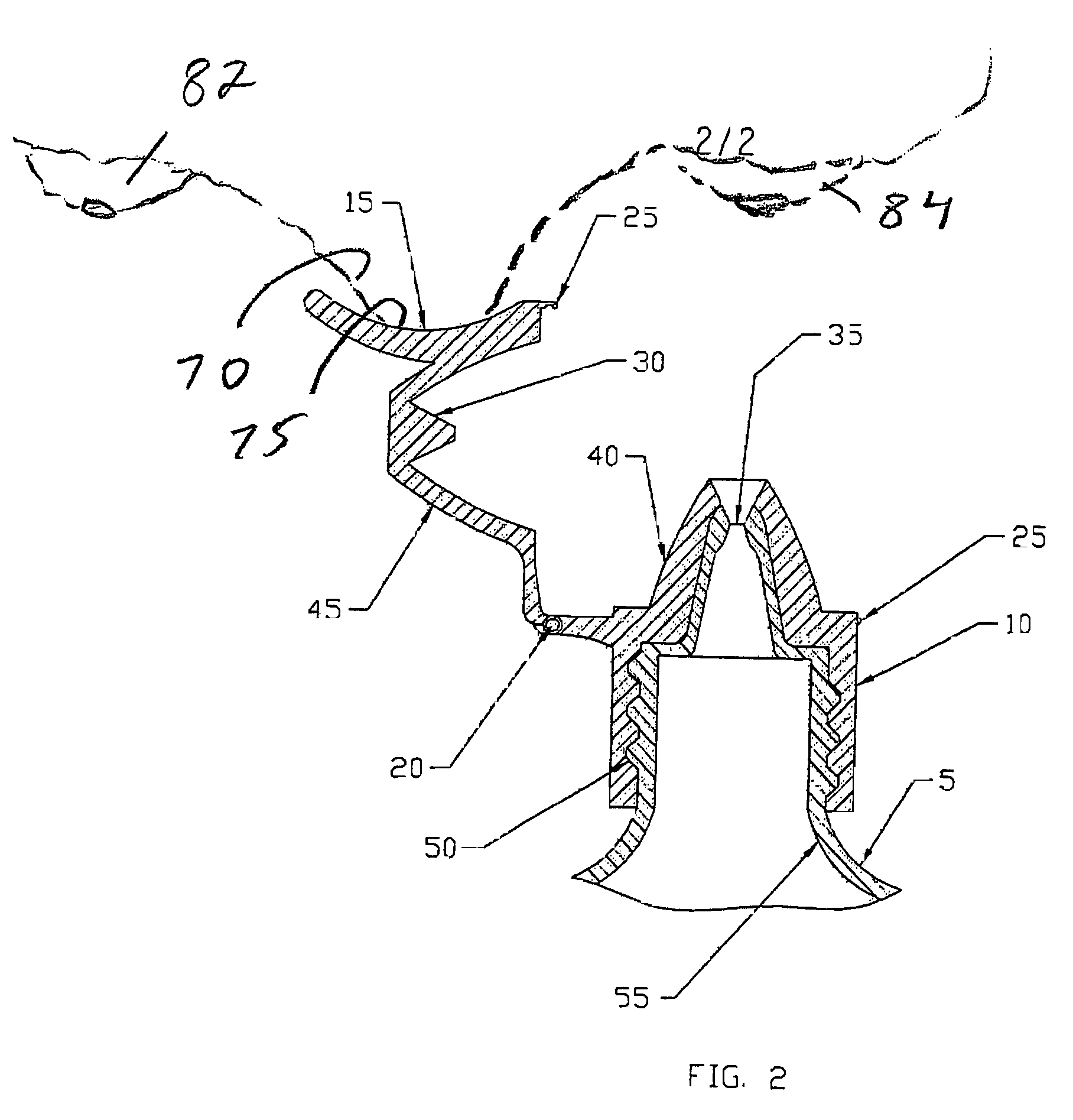
[0012]The ocular positioning droplet dispensing device 10 of the present invention is intended for delivery of sterile fluids such as ophthalmic fluids intended for administration to the eye, comprises briefly two parts. Attaching mechanism 40 having female threads 50 for attaching the droplet dispensing device 10 to the droplet bottle 5 and providing a recessed dispensing orifice 35 that protects the contents of the droplet bottle 5 from contact with septic surfaces. The sealing section 45 of the droplet dispensing device 10 is attached to attaching mechanism 40 by a limited motion hinge 20, which limits the motion of the sealing section 45 from the closed position as seen in FIG. 1 to the full open position as seen in FIG. 2. The flexible latch 25 serves to hold the sealing plug 30 in the closed position to prevent leakage of the ophthalmic fluid from the droplet bottle 5. The sealing section 45 of the droplet dispensing device 10 is fitted with a positioning saddle 15 being forme...


PUM


Abstract

An ocular positioning device threadably attached to a standard soft sided squeeze bottle of ophthalmic fluid. The device consists of two parts, an attaching mechanism and a sealing mechanism, connected by a hinge with motion limited to ninety degrees of arc. The sealing mechanism is fitted with a nose bridge saddle designed to rest on the bridge of the users nose and to align the discharge nozzle with the central portion of the ocular opening of either of the users eyes when the attaching hinge is in the fully open position. The sealing mechanism is also fitted with a manually operated latch to maintain the sealing mechanism in the closed and sealed condition to prevent leakage when not in use.

Description

BACKGROUND[0001]1. Field of Invention[0002]This invention relates to eye drop dispensers and more specifically to eye drop dispensers having recessed dispensing orifice and alignment attachment to position the dispensing orifice over the approximate center of the ocular opening.[0003]2. Description of Prior Art[0004]Liquid eye drops are commonly used to introduce over the counter and prescription medication into the eyes of human patients. The most common container in which these eye drops are supplied is simply a flexible plastic bottle having a tapered dropper. It has been recognized that a flexible bottle with a tapered dropper does not provide optimum means for administering drops into the eye. A significant problem with previous dispensing devices used for dispensing ophthalmic solutions is contamination of the dropper nozzle by inadvertent contact with septic surfaces such as fingertips and facial surfaces. This contact also can clog the dispensing orifice making it impossible...

Claims


Application Information

Patent Timeline
Patent Type & Authority Patents(United States)
IPC IPC(8): B65D47/18
CPCA61F9/0026
Inventor BARBER, RORY
Owner BARBER RORY
Why Eureka
Try Eureka