Method and apparatus for installing and removing a sink mounted garbage disposer

a technology of garbage disposer and sink, which is applied in the direction of work holders, metal-working machine components, manufacturing tools, etc., can solve the problems of affecting the operation of the disposal device, the installation and removal of the garbage disposer is both awkward and physically difficult, and the relative weight of the unit is prone to fall downwards

Inactive Publication Date: 2000-11-07
IRWIN LAWRENCE F
View PDF11 Cites 26 Cited by
  • Summary
  • Abstract
  • Description
  • Claims
  • Application Information

AI Technical Summary

Problems solved by technology

Usually, the kitchen sink is mounted in the top of the kitchen cabinet and only limited access to the disposer is possible via the front doors of the kitchen cabinet.
Because of the location of the garbage disposer, its installation and removal is both awkward and physically difficult.
In this rather awkward position the garbage disposer must be rotated relative to the sink mounting assembly so that it can either be connected to or disconnected from the sink mounted assembly.
Extreme care must be taken in the disposer disconnection operation because once the mounting ring of the garbage disposer is disconnected from the sink mounting assembly, the relatively heavy unit has a tendency to fall downwardly.
In removing old garbage disposers this operation can be difficult because the mounting ring may have become corroded and therefore, extremely difficult to rotate relative to the sink mounting assembly.
Often during the step of forcibly rotating the garbage disposer to free it from the sink mounting assembly the heavy garbage disposer unit will fall and severely injure the installer whose hands and arms may be at least partially positioned beneath the garbage disposer.
Installing the garbage disposer is equally difficult since the installer must usually position his or her head and shoulders inside the kitchen cabinet, hold the heavy disposer with one hand so as to raise it into a position where it can rotatably connected to the sink mounting assembly, and then rotate the unit relative to the sink mounting assembly to sealably interconnect the disposer thereto.
Because of the confined space within which the installer must operate in installing and removing the garbage disposer, little room is left for mechanisms that can aid the workman in the installation task.

Method used


Image

  • Method and apparatus for installing and removing a sink mounted garbage disposer
  • Method and apparatus for installing and removing a sink mounted garbage disposer
  • Method and apparatus for installing and removing a sink mounted garbage disposer

Examples


Embodiment Construction

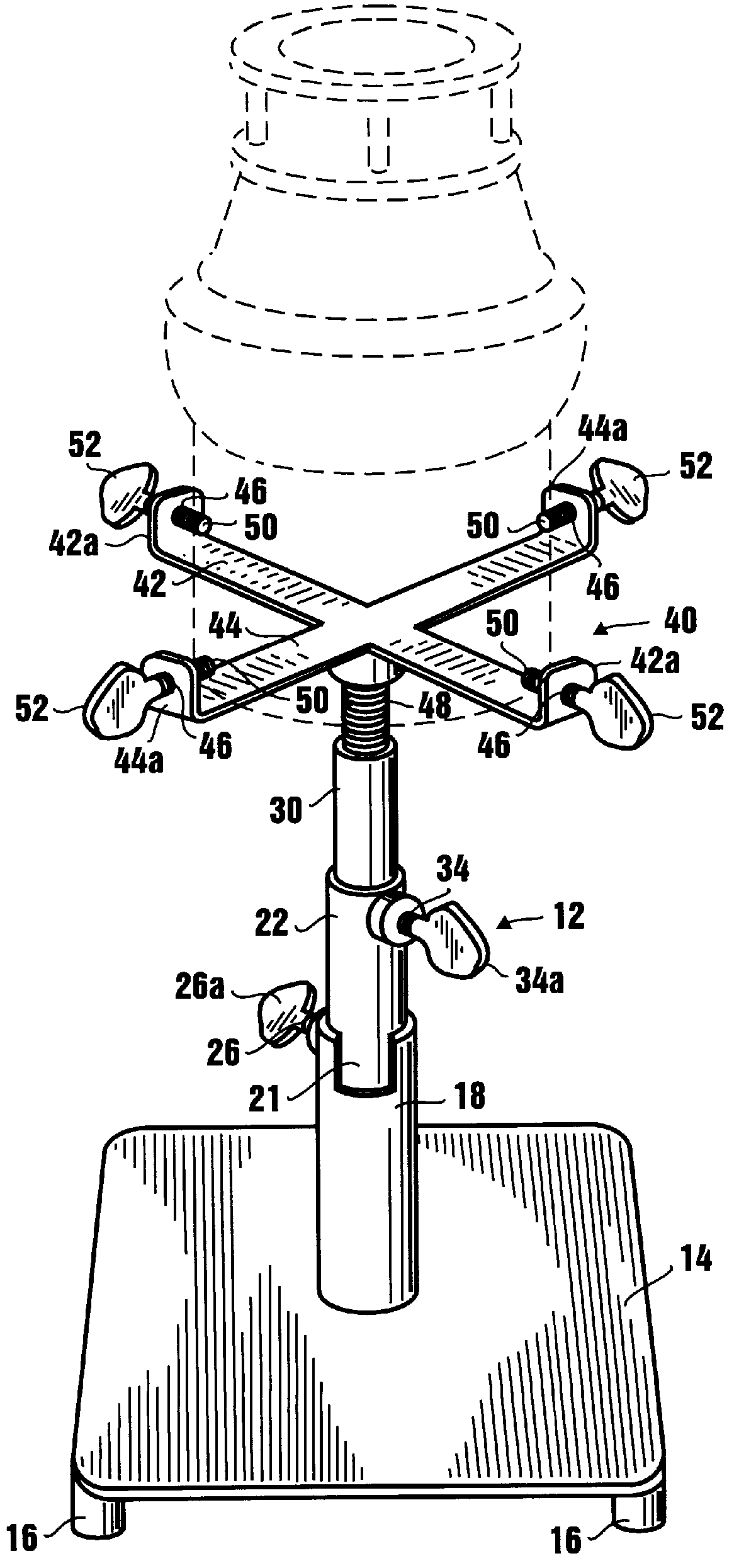
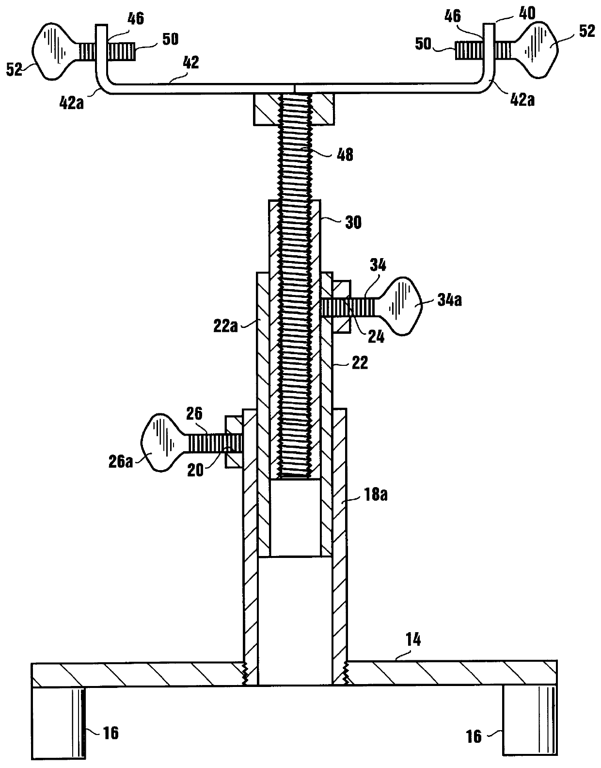
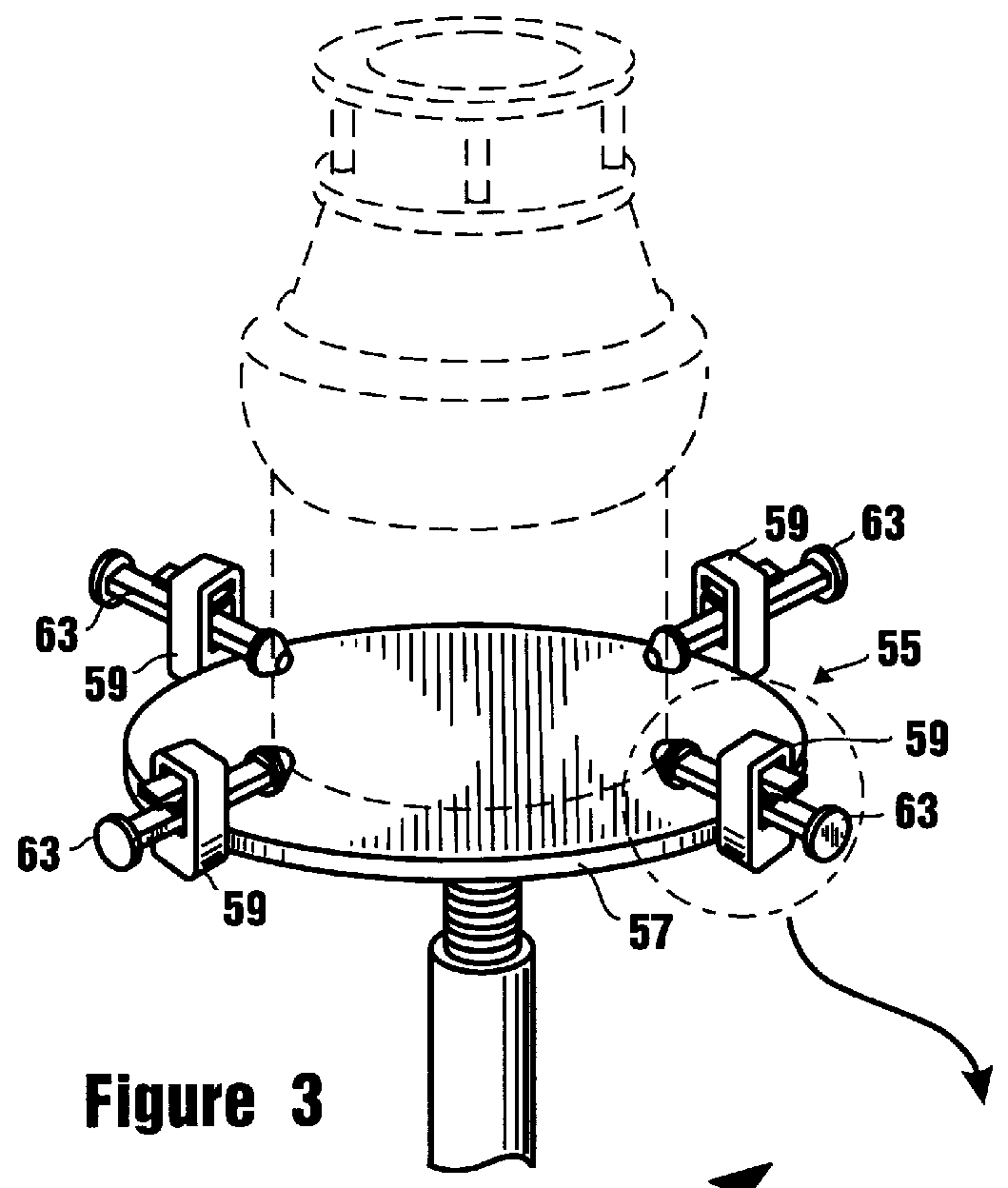
Referring to the drawings and in particularly to FIGS. 1 and 2, one form of the apparatus of the present invention for installing and removing a sink mounted garbage disposer is there illustrated and generally designated by the numeral 12. As best seen by referring to FIG. 1, the apparatus here comprises a generally rectangular shaped base 14 having a plurality of floor engaging feet 16. A first tube 18 having a first inside diameter is mounted on said base and extends generally perpendicularly upwardly therefrom. Tube 18 has an exterior wall 18a which is provided with a transverse threaded bore 20 which extends therethrough (FIG. 2) and a slot 21, the purpose of which will presently be described. A second tube 22 is telescopically receivable within first tube 20 for movement upwardly and downwardly with respect thereto. Second tube 22 also has an exterior wall 22a which is provided with a transverse threaded member 34 which extends therethrough. A first means is provided for lockin...


PUM


Abstract

A method and apparatus for installing and removing sink mounted garbage disposers in a manner which safeguards against injury of the installer. The apparatus of the invention is compact, lightweight and easy to position within the confines of a kitchen cabinet at a location directly beneath the sink mounting assembly to which the garbage disposer is interconnected. The apparatus has both fine and course elevation adjustment capabilities thereby making it easy to use in both the installation and removal of sink mounted garbage disposers of wide variety of sizes and shapes.

Description

1. Field of the InventionThe present invention relates generally to adjustable article support devices. More particularly, the invention concerns an adjustable device for use in installing and removing a sink mounted garbage disposer. The invention also concerns the method of using the apparatus for installing and removing a sink mounted garbage disposer.2. Discussion of the Prior ArtIn recent years it has become common practice in new construction to install with each new kitchen sink an electrically operated garbage disposer. Similarly, it has become routine to install electrically operated garbage disposers in existing kitchens. Typically, the modern garbage disposer is rotatably connected to a sink mounting assembly which is, in turn, connected to a sink sleeve that extends downwardly from the bottom of the kitchen sink. Usually, the kitchen sink is mounted in the top of the kitchen cabinet and only limited access to the disposer is possible via the front doors of the kitchen ca...

Claims


Application Information

Patent Timeline
Patent Type & Authority Patents(United States)
IPC IPC(8): B25B11/00B25B5/10B25B5/00
CPCB25B11/00B25B5/10
Inventor IRWIN, LAWRENCE F.
Owner IRWIN LAWRENCE F
Why Eureka
Try Eureka