Method and circuitry for identifying type of plug connected to a dual-use jack

a dual-use jack and plug technology, applied in the direction of stereophonic circuit arrangement, coupling device connection, instruments, etc., can solve the problems of pop-noise, voltage activated headphone or speaker, etc., to reduce or eliminate pop-noise

Inactive Publication Date: 2013-10-15
LAPIS SEMICON CO LTD
View PDF5 Cites 0 Cited by
  • Summary
  • Abstract
  • Description
  • Claims
  • Application Information

AI Technical Summary

Benefits of technology

[0007]It is an object of the present invention to provide a method of determining usage of a dual-use jack with a reduced pop-noise or no pop-noise.
[0008]Another object of the present invention is to provide a circuitry for determining the usage of a dual-use jack with a reduced or no pop-noise.
[0009]According to a first aspect of the present invention, there is provided an improved method of determining a plug type in use (i.e., a type of a plug connected to a dual-use jack), based on a load resistance of the plug connected to the dual-use jack. The method includes causing an electric current to flow through the load resistance in a first direction. The method also includes comparing a voltage across the load resistance to a reference voltage to determine the plug type in use. The method also includes causing another electric current to flow through the load resistance in a second direction. The second direction is different from the first direction. By causing the electric current to flow in the second direction, a pop-noise is eliminated or reduced. The plug may be a headphone plug or a line output plug. The current flowing in the first direction may have the same absolute value as the current flowing in the second direction, but may have an opposite polarity to the current flowing in the second direction. Time for causing the first current to flow in the first direction may be equal to time for causing the second current to flow in the second direction in one embodiment, but it may be different from time for causing the second current to flow in the second direction in another embodiment.

Problems solved by technology

When a voltage is applied to the plug and jack while the plug is received in the dual-use jack, the voltage activates the headphone or speaker and creates a pop-noise.

Method used


Image

  • Method and circuitry for identifying type of plug connected to a dual-use jack
  • Method and circuitry for identifying type of plug connected to a dual-use jack
  • Method and circuitry for identifying type of plug connected to a dual-use jack

Examples


Embodiment Construction

[0018]Hereinafter, embodiments of the present invention will be described in detail with reference to the accompanying drawings.

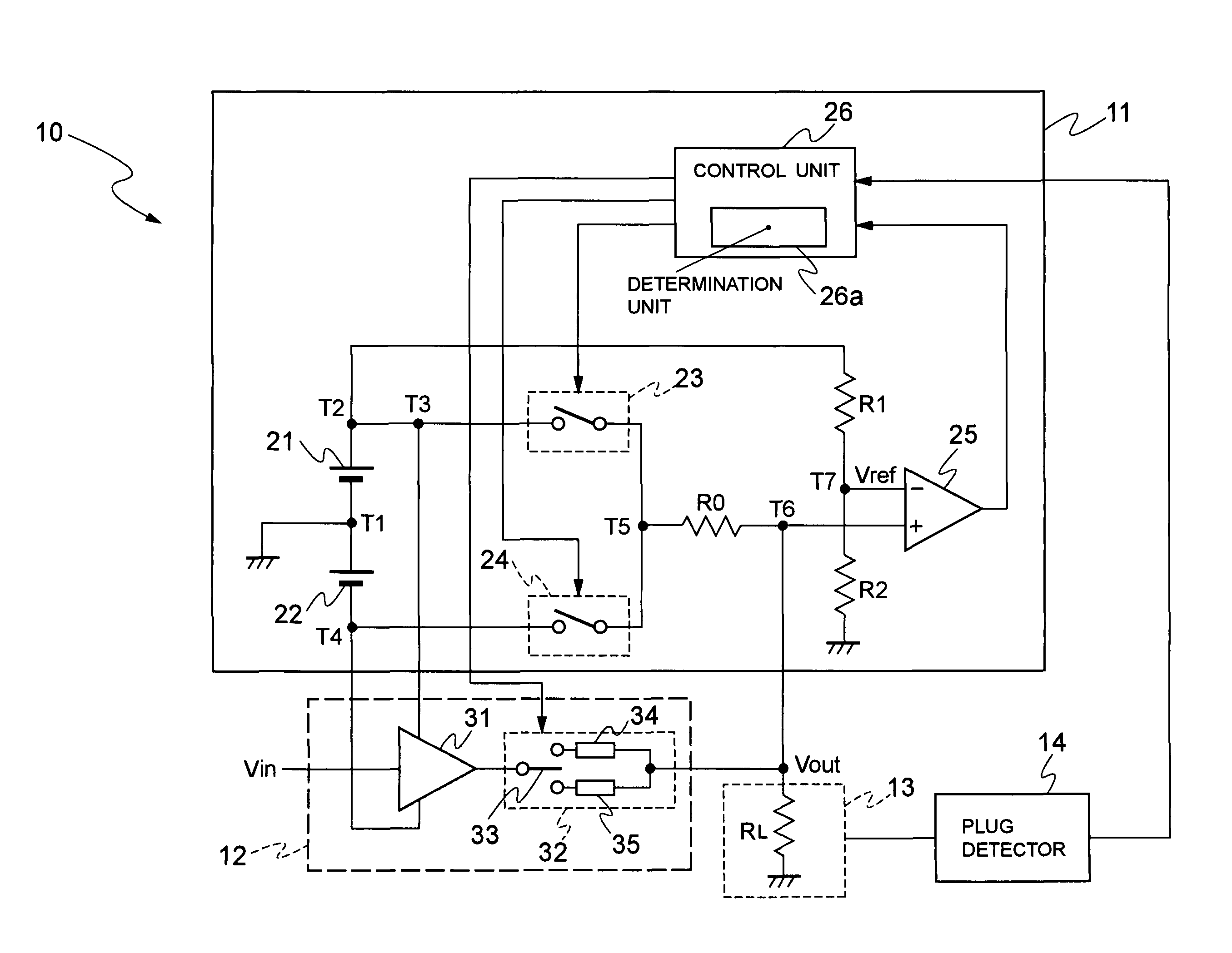
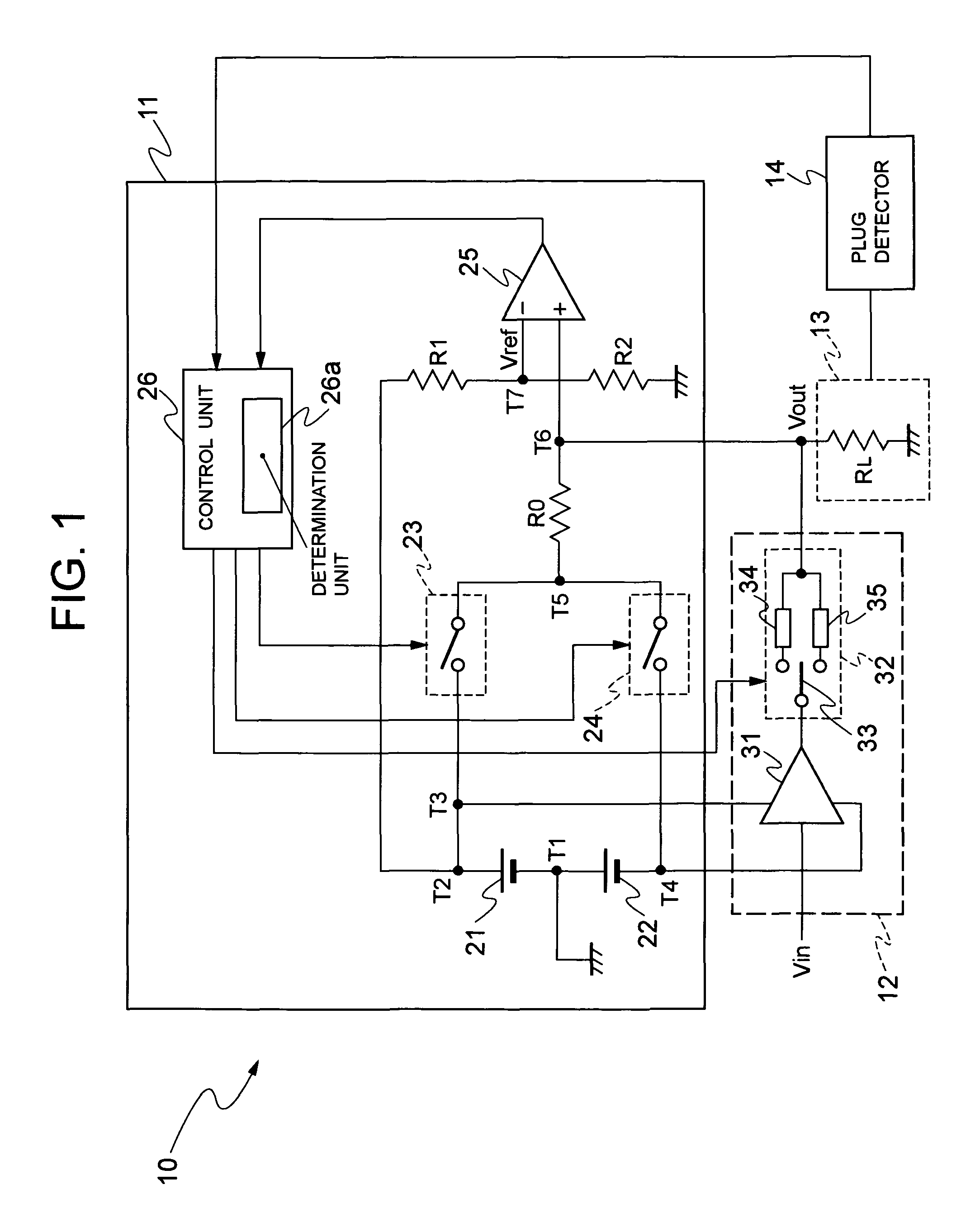
[0019]Referring to FIG. 1, a signal output device 10 will be described. Typically, the signal output device 10 is located inside a portable electronic device such a portable audio player, digital camera and digital video camera.

[0020]As shown in FIG. 1, the signal output device 10 includes a plug type determination circuit 11, an output control circuit 12, a jack 13 and a plug detector 14. The jack 13 is a dual-use jack that can receive a headphone plug or a line output plug in this embodiment.

[0021]The plug type determination circuit 11 has a first power source 21, second power source 22, first switch 23, second switch 24, resistances R0, R1, R2, comparator 25 and control unit 26. The first switch 23 takes an on condition or an off condition, and the second switch 24 also takes an on condition or an off condition. The control unit 26 has a determination pa...


PUM


Abstract

This method is applied to a dual-use jack of an electronic device. Either a headphone plug or a line output plug is inserted into the dual-use jack. The method determines the type of a plug connected to the dual-use jack when the plug is inserted into the dual-use jack. The determination is made based on a load resistance of the plug connected to the jack. The method includes feeding an electric current through the load resistance in a first direction. The method compares a voltage across the load resistance to a reference voltage and determines the type of the plug in use. The method also includes feeding an electric current through the load resistance in a second direction. This electric current can reduce or eliminate a pop-noise when the plug type is determined. The second direction is different from the first direction.

Description

BACKGROUND OF THE INVENTION[0001]1. Field of the Invention[0002]The present invention generally relates to a dual-use jack, which is an audio signal output jack, designed to receive a headphone plug or a line output plug, and more particularly to a method and circuitry for determining whether a headphone plug or a line output plug is connected to the dual-use jack.[0003]2. Description of the Related Art[0004]Portable electronic devices such as portable audio players, digital cameras and digital video cameras have a jack for headphone. With function and performance developments of the portable electronic devices as well as wide spread use thereof, the portable electronic devices are also equipped with another jack (i.e., stereo terminal) that is used for line output.[0005]Separately providing one jack for headphone and another jack for line output will hinder size reduction and weight reduction of the portable electronic device. Thus, a single jack (or dual-use jack) is often used, w...

Claims


Application Information

Patent Timeline
Patent Type & Authority Patents(United States)
IPC IPC(8): G01R27/08H04R1/10
CPCH04R5/04G01R31/043H01R13/703G01R31/68
Inventor SAITO, NAOTAKA
Owner LAPIS SEMICON CO LTD
Why Eureka
Try Eureka