Reconfigurable, non-oscillating liquid lens and imaging systems

a liquid lens and imaging system technology, applied in the field of liquid lens, can solve the problems of slow optical focusing process, and achieve the effect of facilitating the configuration adjustment and facilitating the drop of liquid lens

Active Publication Date: 2013-10-22
RENESSELAER POLYTECHNIC INST
View PDF11 Cites 6 Cited by
  • Summary
  • Abstract
  • Description
  • Claims
  • Application Information

AI Technical Summary

Benefits of technology

[0006]The shortcomings of the prior art are overcome and additional advantages are provided through the provision, in one aspect, of a non-oscillating liquid lens. The non-oscillating liquid lens includes a substrate comprising at least one channel extending through the substrate between a first surface and a second surface of the substrate, and a liquid lens drop comprising a first liquid. The liquid lens drop is held at least partially within one channel of the at least one channel extending through the substrate, and includes a first droplet portion with a first capillary surface protruding away from the first surface of the substrate, and a second droplet portion with a second capillary surface protruding away from the second surface of the substrate. The first droplet portion and the second droplet portion are connected through the one channel. The liquid lens further includes an enclosure which at least partially surrounds the substrate, and which includes a chamber. The one channel of the at least one channel extending through the substrate resides within the chamber of the enclosure. A second liquid is disposed within the chamber, and the second liquid and the liquid lens drop comprising the first liquid are in either direct or indirect contact within the chamber. The liquid lens further includes an actuator which facilitates adjusting configuration of the liquid lens drop within the one channel within the chamber, wherein adjusting configuration of the liquid lens drop adjusts a focal distance of the liquid lens.
[0007]In another aspect, an imaging system is provided which includes a non-oscillating liquid lens and at least one image sensor. The non-oscillating liquid lens includes a substrate comprising at least one channel extending through the substrate between a first surface and a second surface of the substrate, and a liquid lens drop comprising a first liquid. The liquid lens drop is at least partially held within one channel of the at least one channel extending through the substrate, and includes a first droplet portion with a first capillary surface protruding away from the first surface of the substrate, and a second droplet portion with a second capillary surface protruding away from the second surface of the substrate. The first droplet portion and the second droplet portion are connected through the one channel. The liquid lens further includes an enclosure, which at least partially surrounds the substrate, and includes a chamber, wherein the one channel of the at least one channel extending through the substrate resides within the chamber of the enclosure. A second liquid is disposed within the chamber, and the second liquid and the liquid lens drop comprising the first liquid are in either direct or indirect contact within the chamber. An actuator is provided which facilitates adjusting configuration of the liquid lens drop held within the one channel within the chamber, wherein adjusting configuration of the liquid lens drop adjusts a focal distance of the liquid lens. The at least one imaging sensor is coupled to at least one imaging path passing through the first and second droplet portions of the liquid lens drop held at least partially in the one channel for capturing an image through the first and second droplet portions of the liquid lens drop.

Problems solved by technology

Optical focusing is often a slow process due to the delay inherent in moving mechanically a camera's lens until an image is in focus.

Method used


Image

  • Reconfigurable, non-oscillating liquid lens and imaging systems
  • Reconfigurable, non-oscillating liquid lens and imaging systems
  • Reconfigurable, non-oscillating liquid lens and imaging systems

Examples


Embodiment Construction

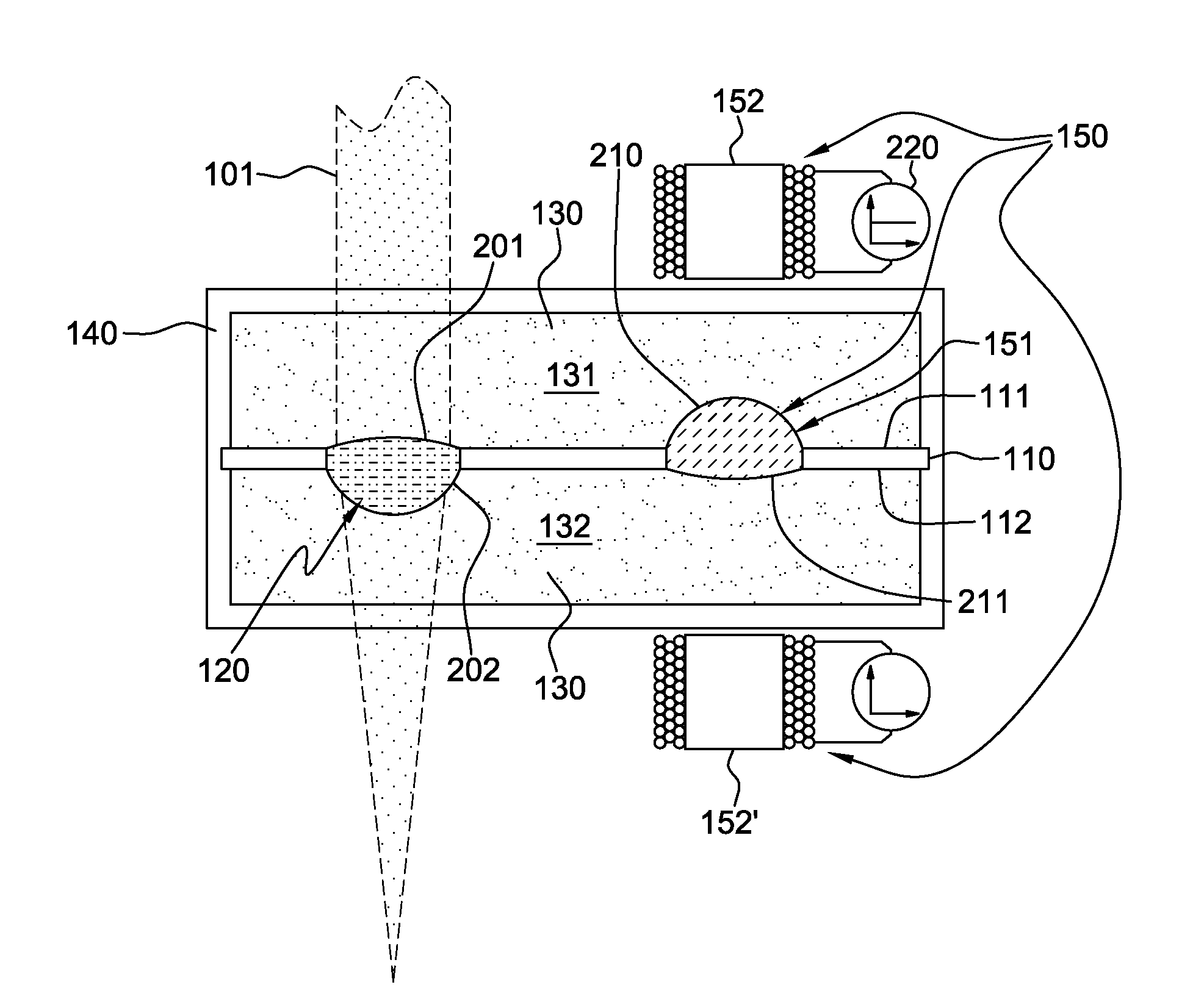
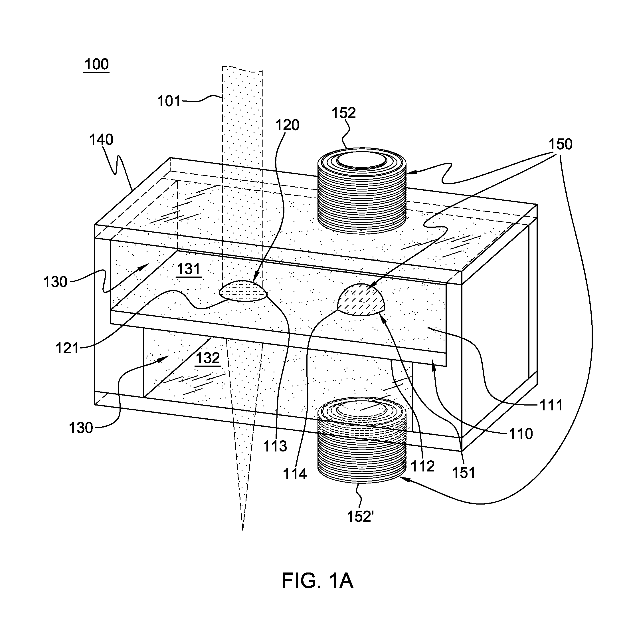
[0029]Disclosed herein is a reconfigurable, non-oscillating liquid lens with an actuator (or driver) for adjusting configuration of a liquid lens drop, and thus a focal distance of the reconfigurable, non-oscillating liquid lens. The reconfigurable, non-oscillating liquid lens is stable (or static) once configured, and is ideal for lower-power applications and those requiring long exposure time, such as low-light imaging. As explained further below, in certain embodiments, once a new lens configuration is achieved (i.e., a desired focal distance is obtained), no further energy or power input is needed to maintain or hold that liquid lens configuration.

[0030]While certain strategies have used membranes to contain a liquid lens, of particular interest is a liquid lens constrained only by the surface tension itself, primarily due to the deleterious effects of the membrane on image quality and the manufacturing challenges in producing a uniform and long-lasting membrane. However, even s...


PUM

PropertyMeasurementUnit
diameteraaaaaaaaaa
diameteraaaaaaaaaa
focal distanceaaaaaaaaaa

Abstract

A non-oscillating liquid lens and imaging system and method employing the lens are provided. The liquid lens includes a substrate with a channel opening extending through the substrate. A liquid lens drop is held within the channel and is sized with a first droplet portion, including a first capillary surface, protruding away from a first substrate surface, and a second droplet portion, including a second capillary surface, protruding away from a second substrate surface. The liquid lens further includes an enclosure at least partially surrounding the substrate, and which includes a chamber. The liquid lens drop resides within the chamber, and the liquid lens includes a second liquid disposed within the chamber in direct or indirect contact with the liquid lens drop, and an actuator which facilitates adjusting configuration of the liquid lens drop within the channel, and thus, a focal distance of the liquid lens.

Description

CROSS-REFERENCE TO RELATED APPLICATION[0001]This application claims the benefit of U.S. Provisional Patent Application No. 61 / 368,020, filed Jul. 27, 2010, which is hereby incorporated herein by reference in its entirety.STATEMENT REGARDING FEDERALLY SPONSORED RESEARCH[0002]This invention was made with support from the Defense Advanced Research Projects Agency (DARPA) of the Department of Defense of the United States of America, under Contract No. HR001-09-1-0052. Accordingly, the United States government may have certain rights in the invention.BACKGROUND[0003]The present invention relates in general to adaptive optical devices, and more particularly, to liquid lenses, and to imaging systems and imaging methods employing the same.[0004]Optical focusing is often a slow process due to the delay inherent in moving mechanically a camera's lens until an image is in focus. Although liquids are considered an exotic choice for lens material, there is interest in liquid lenses for applicati...

Claims


Application Information

Patent Timeline
Patent Type & Authority Patents(United States)
IPC IPC(8): G02B1/06G02B15/14
CPCB29D11/00461G02B3/14Y10T29/4998
Inventor HIRSA, AMIR H.MALOUIN, JR., BERNARD A.VOGEL, MICHAEL J.
Owner RENESSELAER POLYTECHNIC INST
Why Eureka
Try Eureka