

Thermoelectric generator and fuel cell for electric power co-generation
a technology of electric power co-generation and fuel cells, applied in the field of electric power generation, can solve the problems of merely representation and may not be drawn to scal
- Summary
- Abstract
- Description
- Claims
- Application Information
AI Technical Summary
Problems solved by technology
Method used
Image

Examples
first embodiment
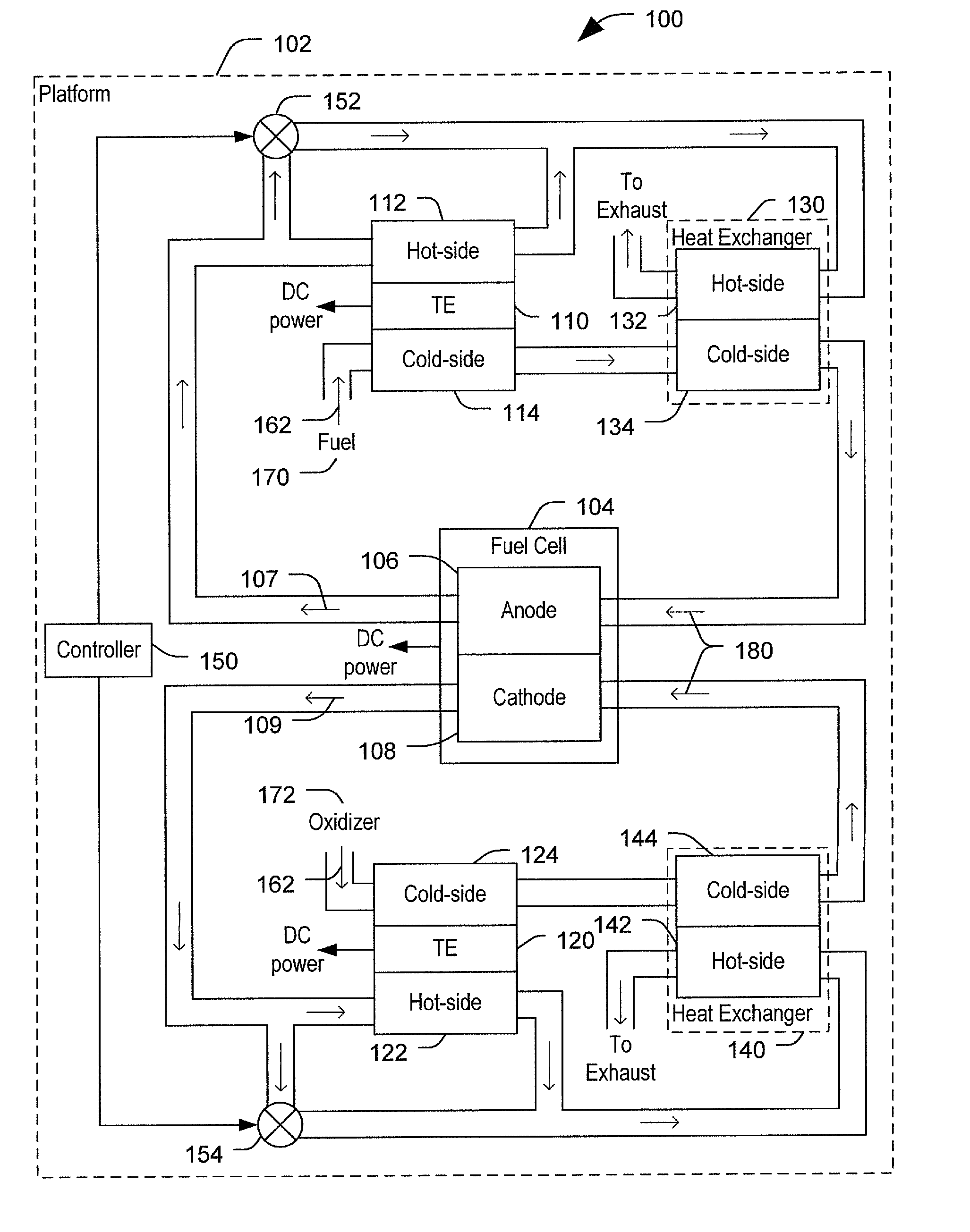
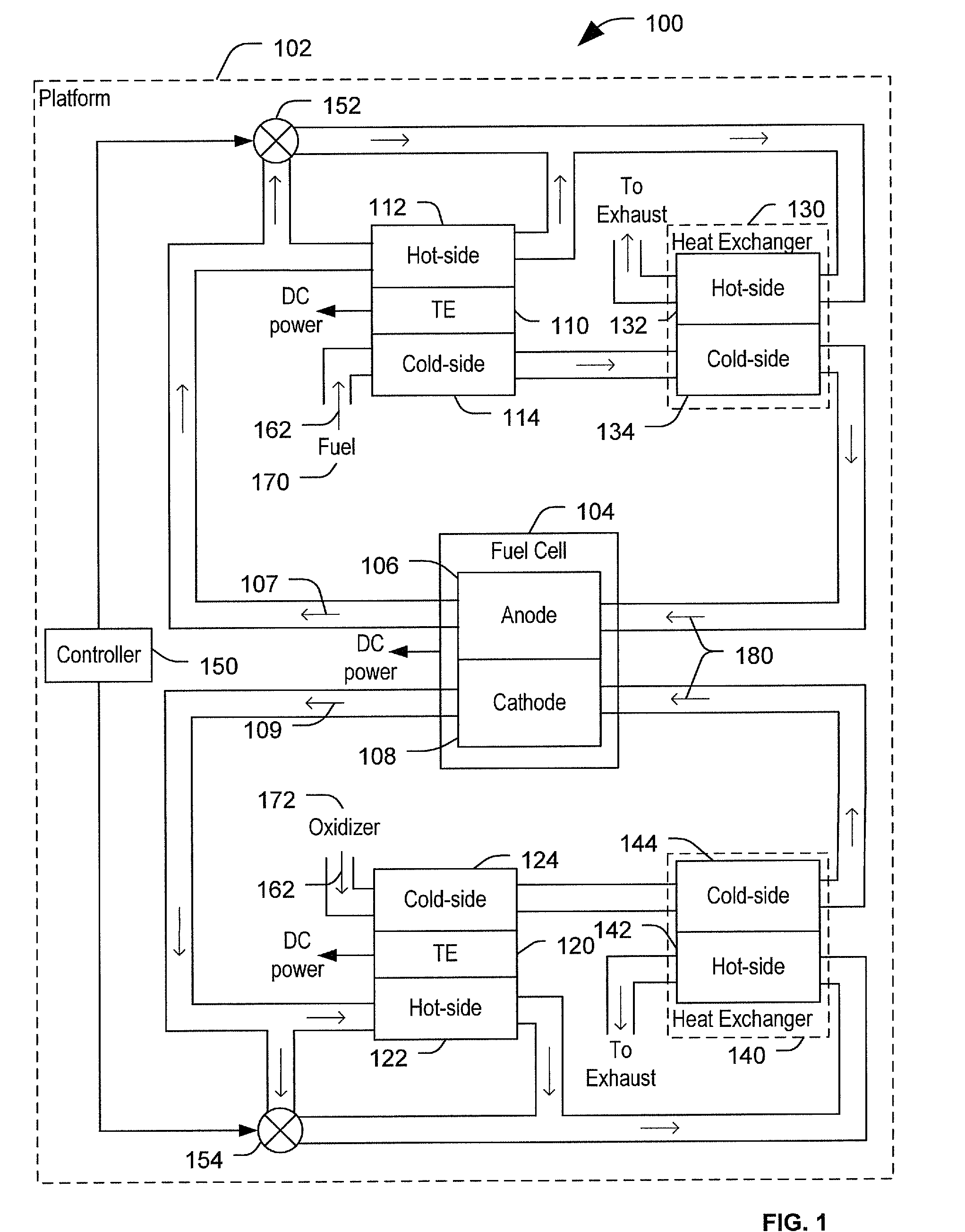
[0017]FIG. 1 is a diagram of a system to generate electric power, the system generally designated 100. The system 100 includes a platform where a power generation system is situated. For example, the platform can be a mobile platform, such as an aircraft, a space craft, a watercraft, or a land-based vehicle. In another example, the platform can be a stationary platform, such as a power generation system in a utility power plant, an industrial site, an office building, or another substantially stationary structure. In a particular embodiment, the power generation system of the platform 102 includes components to generate electric power. For example the components to generate electric power may include a fuel cell 104 having an anode 106 and a cathode 108. The components to generate electric power may also include one or more thermoelectric generators (TE), such as a first TE 110 and a second TE 120.
[0018]In a particular embodiment, the first TE 110 is coupled to the anode 106 of the ...
second embodiment
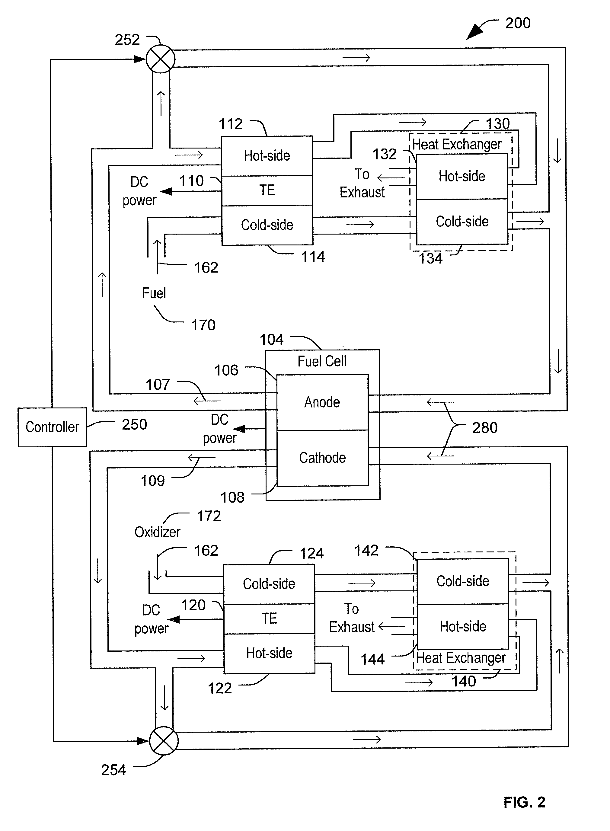
[0023]FIG. 2 is a diagram of a system to generate electric power, the system generally designated 200. In a particular embodiment, the system 200 includes many elements that are the same as or substantially similar to elements of the system 100. Such elements have the same reference number as in FIG. 1 for ease of reference and description.
[0024]In the system 200, a controller 250 controls one or more control valves 252, 254. The control valves 252, 254 are positioned between a fuel cell outlet and a fuel cell inlet (rather than between the fuel cell outlet and the heat exchanger hot-side inlet as in the system 100 of FIG. 1). Thus, the control valves 252, 254 control an amount of the hot exhaust gases 107, 109 that bypass both the TEs 110, 120 and the heat exchanger 130, 140. The control valves 252, 254 are operable to control preheating of preheated intake gas 280 routed to the fuel cell by controlling a portion of the hot exhaust gases 107, 109 that is mixed directly into the pre...
third embodiment
[0025]FIG. 3 is a diagram of a system to generate electric power, the system generally designated 300. In a particular embodiment, the system 300 includes many elements that are the same as or substantially similar to elements of the system 100. Such elements have the same reference number as in FIG. 1 for ease of reference and description.
[0026]In the particular embodiment of FIG. 3, no heat exchangers, such as the heat exchangers 130 and 140 of FIGS. 1 and 2, are present. Rather, TEs 310, 320 coupled to outlets of the fuel cell 104 exchange heat between the hot exhaust gases 107, 109 and the intake gases 162 in addition to generating power based on a temperature differential between the hot exhaust gases 107, 109 and the intake gases 162. A controller 350 controls one or more control valves 352, 354 that are positioned between the fuel cell outlet and the fuel cell inlet. Thus, the control valves 352, 354 control an amount of the hot exhaust gases 107, 109 that bypass TEs 310, 320...
PUM
| Property | Measurement | Unit |
|---|---|---|
| temperature | aaaaa | aaaaa |
| temperature | aaaaa | aaaaa |
| temperature | aaaaa | aaaaa |
Abstract
Description
Claims
Application Information