Organic electroluminescence element

a technology of electroluminescence elements and organic materials, which is applied in the direction of luminescence screens, thermoelectric devices, and discharge tubes, etc., can solve the problems of unclear optical design principles for future progress, and the literature 1 fails to disclose the consideration of the phase shift of light, so as to increase the light flux or the effect of photon number

Active Publication Date: 2013-10-29
SAMSUNG DISPLAY CO LTD
View PDF25 Cites 0 Cited by
  • Summary
  • Abstract
  • Description
  • Claims
  • Application Information

AI Technical Summary

Benefits of technology

[0025]In this case, it is possible to increase the light flux which is emitted from the organic electroluminescence element.
[0027]In this case, it is possible to increase the photon number which is emitted from the organic electroluminescence element.
[0029]In this case, it is possible to especially increase the light flux or the photon number which are emitted from the organic electroluminescence element.

Problems solved by technology

However, the patent literature 1 fails to disclose the consideration of the phase shift of the light in the light reflective electrode 2.
However, the principle of the optical design for the future progress is not clear yet.

Method used


Image

  • Organic electroluminescence element
  • Organic electroluminescence element
  • Organic electroluminescence element

Examples


example 1

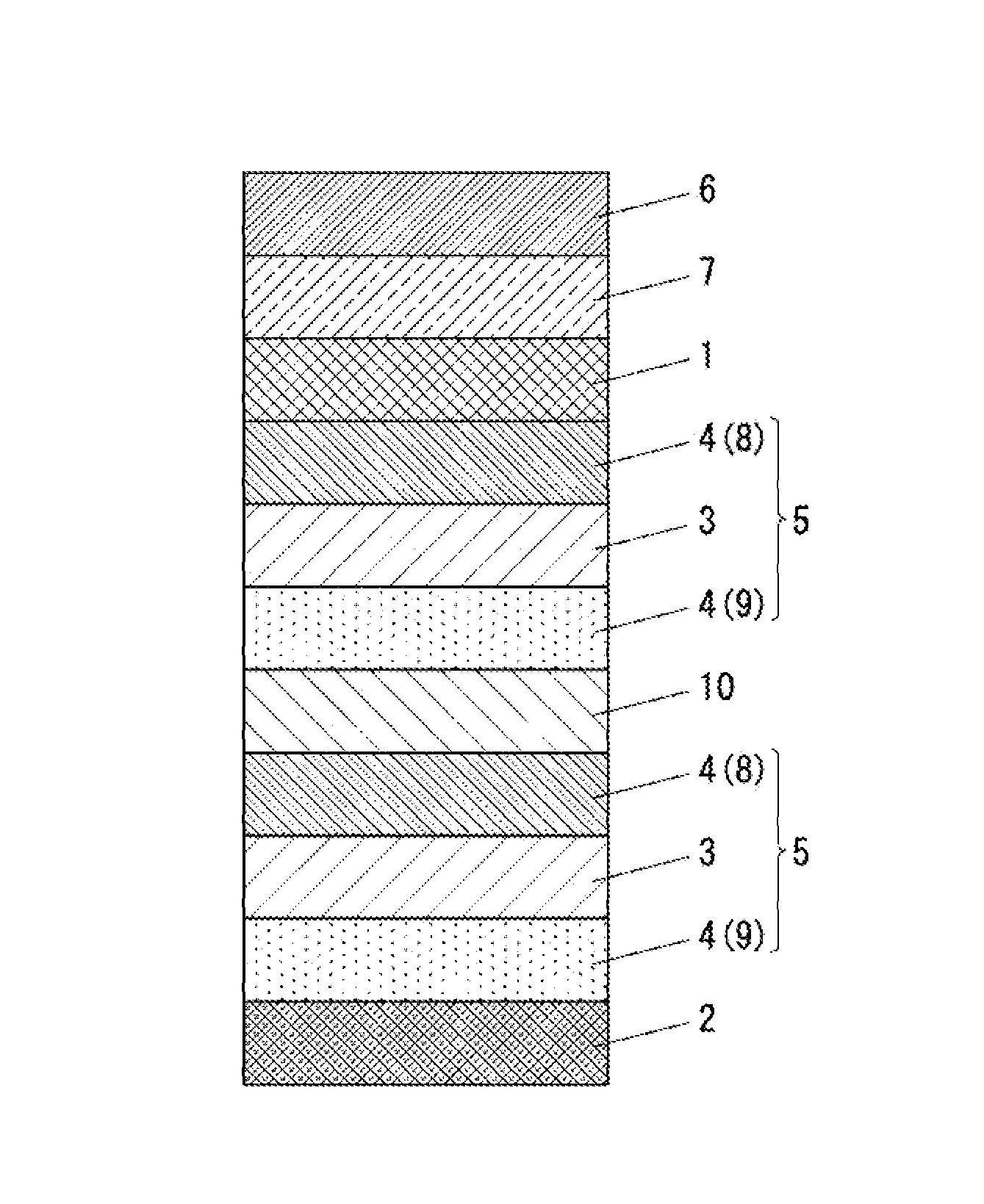
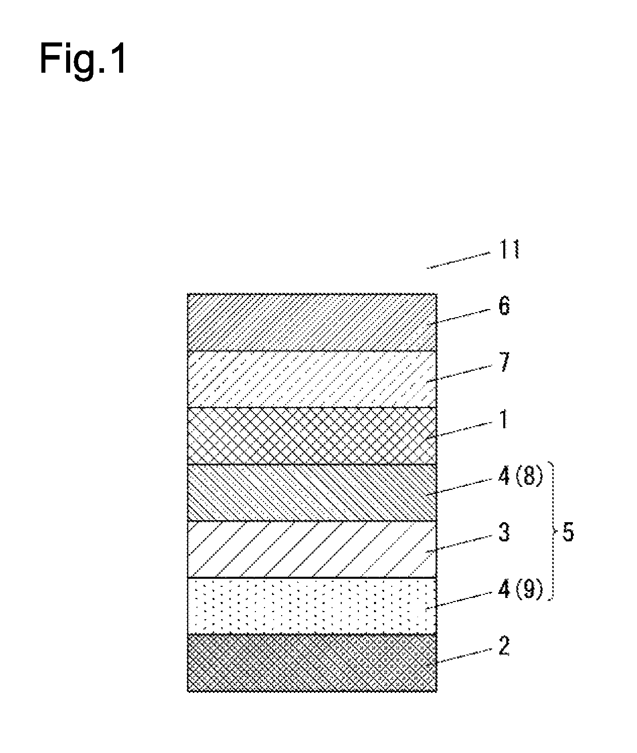
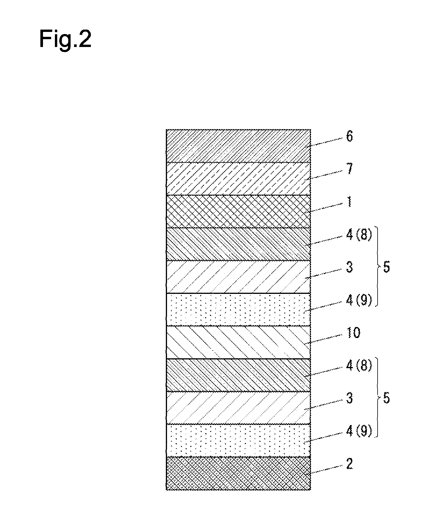
[0093]The light transmissive substrate 6 with the light scattering layer 7 was prepared according to the following steps. In a first, 86.8 g tetraethoxysilane was combined with 803.5 g isopropyl alcohol, and was further combined with 34.7 g gamma-methacryloxypropyl trimethoxysilane and 75 g 0.1-N nitric acid. Then, these were mixed with each other by the disper, whereby solution was obtained. The solution was agitated for 2 hours in the constant temperature reservoir of 40 degree Celsius. Consequently, 5 wt % solution of silicone resin having the weight-average molecular weight of 1050 was prepared as a binder formation material.

[0094]Then, the methyl silicone particles were added to the silicone resin solution. (The methyl silicone particles had mean diameter of 2 micrometer. The methylsilicone particles was Tospearl 120 (GE Toshiba Silicone).) The silicone resin solution has a ratio of the methyl silicone particles:the silicone resin is equal to 80:20 according to the solid conten...

example 2

[0103]The organic electroluminescence element was prepared according to the same condition of the example 1, except for the thickness of the charge transport layer 9; the thickness of the charge transport layer 9 is 235 nm.

example 3

[0104]The organic electroluminescence element was prepared according to the same condition of example 1, except for the thickness of the charge transport layer 9; the thickness of the charge transport layer 9 has a thickness of 350 nm.


PUM


Abstract

The electroluminescence element comprises the light-reflective-electrode separated from the luminous point by distance “d” satisfying the following formula.nd=a×λ4⁢{2⁢m+ϕπ}⁢⁢wherein⁢⁢ϕ=tan-1⁢{2⁢(n1⁢k2-n2⁢k1)n12-n22+k12-k22}λ is a wavelength of the light from the light emission layer. N is a refractive index of a certain layer between the luminous point and the light-reflective-electrode at λ. n1 and k1 is a refractive index and the extinction coefficient of the certain layer at λ. n2 and k2 is a refractive index and the extinction coefficient of the light-reflective-electrode at λ. m is 0 or 1. When “m” is 0, “a” satisfies the following formula.−1.17×norg / nEML+1.94≦a≦−0.16×norg / nEML+2.33When “m” is 1, “a” satisfies the following formula.0.28×norg / nEML+0.75≦a≦2.85×norg / nEML−1.23norg is a refractive index of a predetermined layer in contact with the light emission layer to be located on the same side as the light-reflective-electrode at λ. nEML is a refractive index of the light emission layer at λ.

Description

TECHNICAL FIELD[0001]This invention relates to organic electroluminescence elements which are used for a lighting source, a backlight for the liquid crystal display instrument, and a flat panel display. Specifically, this invention relates to the organic electroluminescence elements which are designed on the basis of the adequate optical design to have a good light emitting property when the light scattering region is provided on the outer surface of the light transmissive substrate, which is defined as a part of the organic electroluminescence element.BACKGROUND ART[0002]FIG. 6 shows one example of the structure of the organic electroluminescence element. The organic electroluminescence element comprises a light transmissive substrate 6, a light transmissive electrode 1 which is defined as an anode, a hole transport layer 8, a light emission layer 3, an electron transport layer 9, and a light reflective electrode 2 defined as a cathode. The light transmissive electrode 1, the hole ...

Claims


Application Information

Patent Timeline
Patent Type & Authority Patents(United States)
IPC IPC(8): H01L35/24
CPCH01L51/5262H01L51/5268H01L51/5271H01L2251/558H10K50/85H10K50/854H10K50/856H10K2102/351H10K50/818
Inventor YAMANA, MASAHITONAKAMURA, MASAHIRO
Owner SAMSUNG DISPLAY CO LTD
Why Eureka
Try Eureka