
Pedicle screw fixation system and method for use of same

a technology of pedicle screw and fixation system, which is applied in the field of pedicle screw fixation system, can solve the problems of reducing the rigidity required during surgery to achieve and maintain accurate placement, and the relative complexity of the locking mechanism for securing the orthopedic rod, so as to achieve the effect of increasing the surface area of conta

Active Publication Date: 2013-11-05
EMINENT SPINE
View PDF12 Cites 15 Cited by
  • Summary
  • Abstract
  • Description
  • Claims
  • Application Information

AI Technical Summary

Benefits of technology

The patent describes a system for fixing a pedicle screw to a bone using a tulip and a coupling collar. The tulip holds the screw in place and the collar securely attaches a rod to the screw. The system allows for polyaxial placement of the screw and secure locking in position using a set screw. The technical effect of this system is improved stability and secure fixation of the screw to the bone, which can lead to better outcomes for patients.

Problems solved by technology

The disadvantages of these pedicle screws includes the relatively complicated locking mechanisms for securing the orthopedic rod into a receiving member or tulip.
In many cases, the head of the pedicle screw can be aligned with the position of the orthopedic rod only to a limited extent, necessitating complicated bending of the longitudinal bar to correct the angle.
These pivoting linkages, while permitting the alignment of the orthopedic rod, have proven themselves to lack the rigidity required during surgery to achieve and maintain an accurate placement.

Method used


Image

  • Pedicle screw fixation system and method for use of same
  • Pedicle screw fixation system and method for use of same
  • Pedicle screw fixation system and method for use of same

Examples


Embodiment Construction

[0017]While the making and using of various embodiments of the present invention are discussed in detail below, it should be appreciated that the present invention provides many applicable inventive concepts which can be embodied in a wide variety of specific contexts. The specific embodiments discussed herein are merely illustrative of specific ways to make and use the invention, and do not delimit the scope of the present invention.

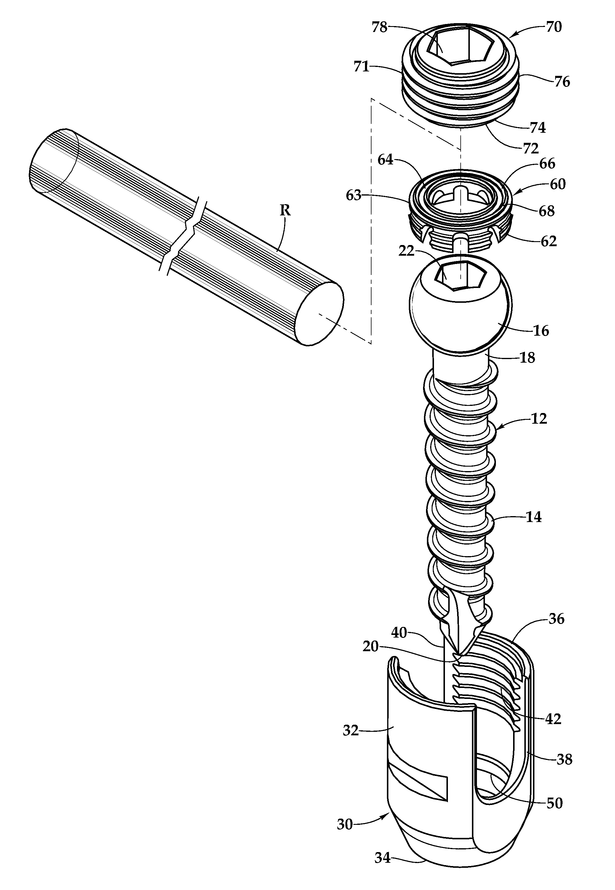
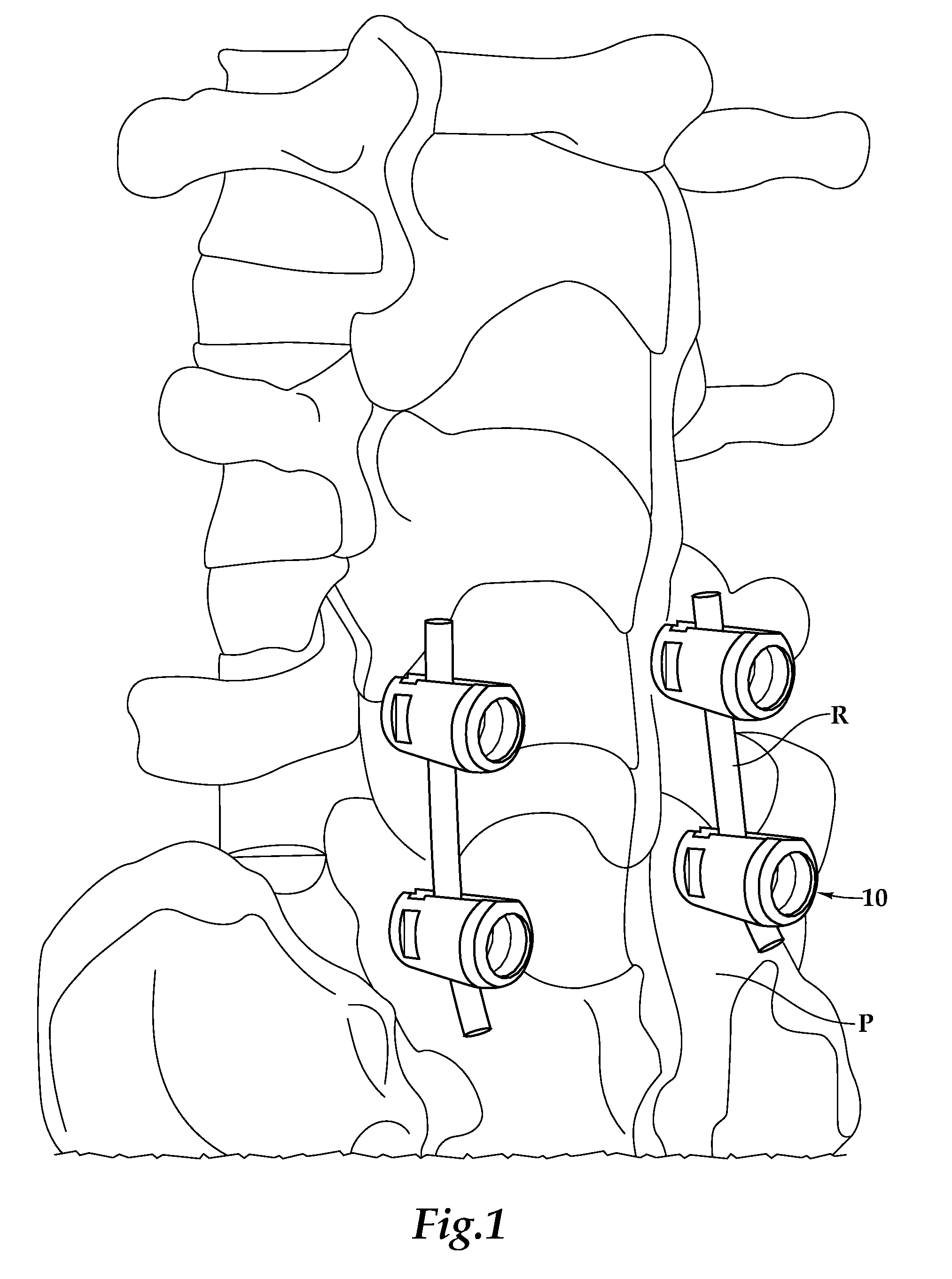
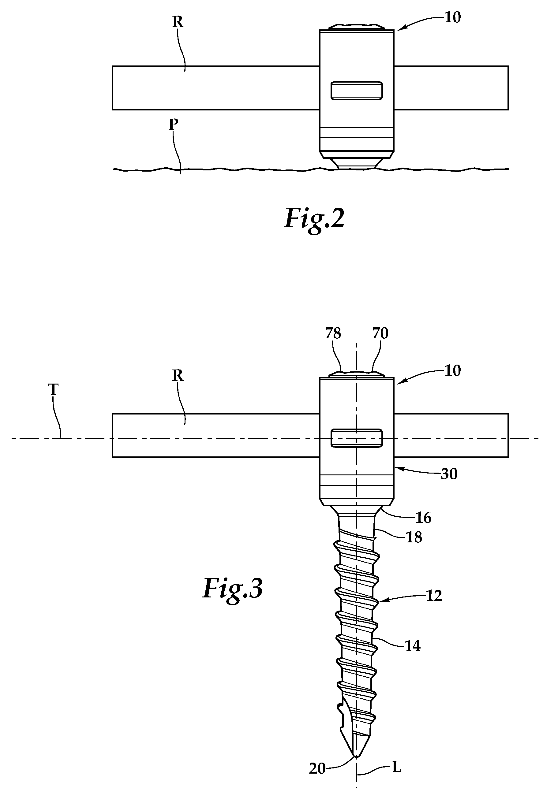
[0018]Referring initially to FIGS. 1 and 2, therein is depicted one embodiment of a set of pedicle screw fixation systems, individually and collectively numbered 10, implanted into a humane vertebral column. A vertebral pedicle is a dense stem-like structure that projects from the posterior of a vertebra. There are two pedicles per vertebra that connect to other structures such as lamina and vertebral arches. By way of example, the pedicle screw fixation system presented herein may be used to correct deformity, treat trauma, or a combination thereof. Ad...


PUM


Abstract

A pedicle screw fixation system and method for use of the same are disclosed. In one embodiment, a tulip is provided for holding a head of a pedicle screw substantially along a longitudinal axis. The tulip includes opposing first and second U-shaped receiving slots aligned along a transverse axis. A rod is received by the opposing first and second U-shaped receiving slots. A coupling collar includes a plurality of resilient fingers circumferentially disposed therearound such that a snap fit engagement with the head of the pedicle screw formed. The coupling collar includes a first deformable face operable for contact with the rod. A set screw is adapted for driving engagement through the tulip along the longitudinal axis such that a second deformable face is positioned for contact with the rod. The first and second deformable faces conform to the shape of the rod in response to forceful engagement therewith.

Description

PRIORITY STATEMENT & CROSS-REFERENCE TO RELATED APPLICATIONS[0001]This application claims priority from patent application Ser. No. 61 / 119,312 entitled “Pedicle Screw Fixation System and Method for Use of Same” and filed on Dec. 2, 2008 in the names of Steve Courtney and David Freehill; which is hereby incorporated by reference for all purposes.TECHNICAL FIELD OF THE INVENTION[0002]This invention relates, in general, to connection of an orthopedic rod to an anchoring element and, in particular, to a pedicle screw fixation system and method for use of the same for surgical use on the spinal column of a patient for stabilization thereof.BACKGROUND OF THE INVENTION[0003]A large number of pedicle screws for fixation of the spinal column are already known. The disadvantages of these pedicle screws includes the relatively complicated locking mechanisms for securing the orthopedic rod into a receiving member or tulip. In many cases, the head of the pedicle screw can be aligned with the pos...

Claims


Application Information

Patent Timeline
Patent Type & Authority Patents(United States)
IPC IPC(8): A61B17/86A61B17/88
CPCA61B17/8605A61B17/7037A61B17/7032A61B17/7034A61B17/8685
Inventor COURTNEY, STEVEFREEHILL, DAVID
Owner EMINENT SPINE
Learn More