
Motor

a multi-motor, electric technology, applied in the direction of dynamo-electric components, ac commutators, dc commutators, etc., can solve the problems of increasing the number of brushes, increasing the cost as well as the size of the motor, and limiting the wave winding to certain motors. , to achieve the effect of reducing the number of brushes and quick winding

Active Publication Date: 2013-11-05
JOHNSON ELECTRIC SA
View PDF6 Cites 2 Cited by
  • Summary
  • Abstract
  • Description
  • Claims
  • Application Information

AI Technical Summary

Benefits of technology

[0019]A motor according to preferred embodiments of the present invention has an even number of segments, therefore the rotor winding may be wound quickly using a dual flyer winding machine. The number of brushes can be reduced by implementing the winding scheme according to the present invention.

Problems solved by technology

The increase in the number of brushes increases the cost as well as the size of the motor.
Therefore, wave windings are limited to some specific motors.
Further more, traditional wave windings are wound by a winding machine using a single flyer due to the odd number of coils, which takes more time than using a dual flyer winding machine.

Method used


Image

  • Motor
  • Motor
  • Motor

Examples


Embodiment Construction

[0028]The present invention provides a motor which comprises a stator having four or more poles and a rotor having an even number of teeth (slots) and a commutator with an even number of segments. The number of the brushes is reduced by implementing the present invention.

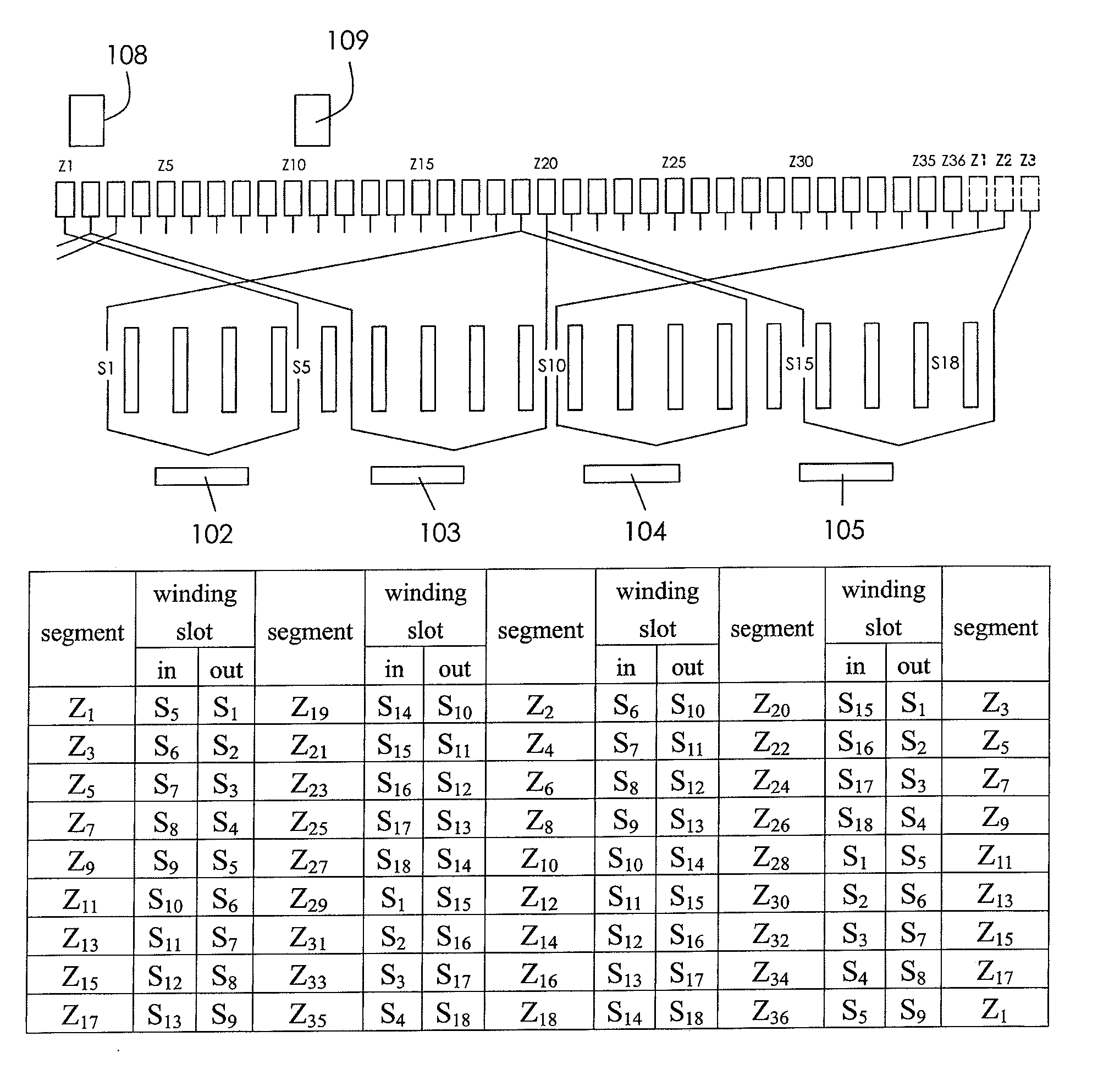
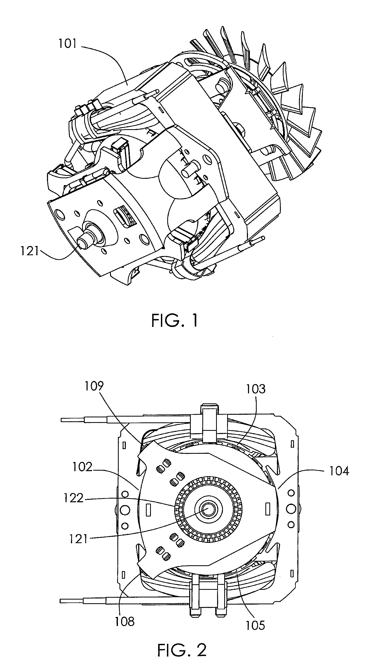
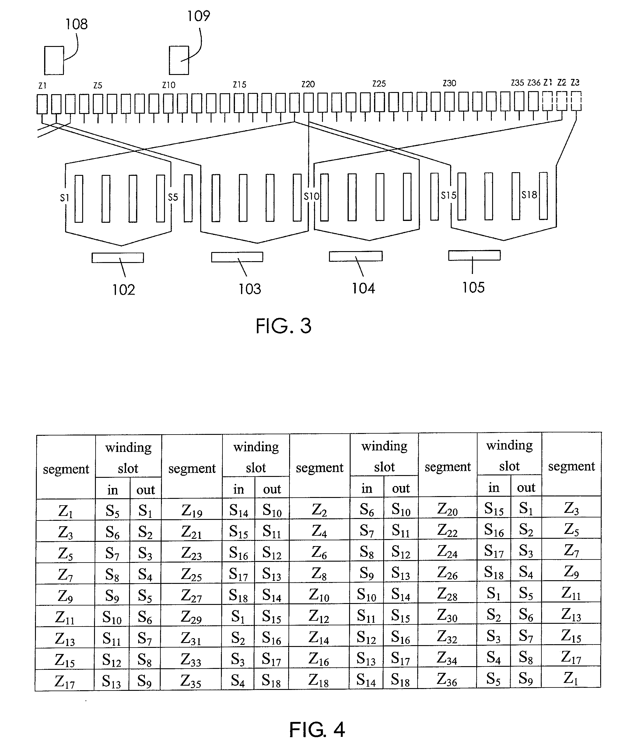
[0029]FIG. 1 illustrates a universal motor according to one preferred embodiment of the present invention, and FIG. 2 is a plan view of the universal motor with a bear bracket removed to reveal the commutator 122. The universal motor according to this embodiment is a single-phase series motor, comprising a stator and a rotor rotatably mounted to and confronting the stator. The stator comprises a stator core 101 and two brushes 108, 109 located at one axial end of the stator. The stator core 101 is formed by stacking laminations in an axial direction of the motor, and comprises a yoke portion and salient poles 102˜105 inwardly extending from the yoke portion, wherein the salient poles 102 and 104 have field coils wou...


PUM


Abstract

A motor has a stator and a rotor. The stator has 2P poles wherein P is an integer greater than one. The rotor has a shaft, a rotor core and a commutator fixed to the shaft. The commutator has m segments where m is an even integer greater than P. Every two adjacent segments are electrically connected by a winding unit so that the rotor winding comprises m winding units with at least one of the winding units comprising P coils connected in series; and each coil of each winding unit is directly connected to a corresponding two segments.

Description

CROSS REFERENCE TO RELATED APPLICATIONS[0001]This non-provisional patent application claims priority under 35 U.S.C. §119(a) from Patent Application No. 200910108820.1 filed in The People's Republic of China on Jul. 20, 2009.FIELD OF THE INVENTION[0002]This invention relates to an electric motor, and in particular to a multi-pole motor which comprises a stator, brushes and a rotor with a commutator. The term “multi-pole motor” as used in the specification and the appended claims, means a motor having four or more stator poles.BACKGROUND OF THE INVENTION[0003]A commutator motor generally comprises a stator having a plurality of stator poles and a rotor having a rotor shaft, a rotor core fixed to the shaft, a commutator fixed to the shaft and a rotor windings wound about poles of the rotor core and electrically connected to segments of the commutator. Brushes transfer electrical power to the windings via the commutator. The number of brushes generally increases with an increase in the...

Claims


Application Information

Patent Timeline
Patent Type & Authority Patents(United States)
IPC IPC(8): H02K23/26
CPCH02K23/34
Inventor LI, YUELIU, BAO TINGPAN, JI CHENGJIANG, MAO XIONGSONG, YONG QIANGCHAI, JI DONG
Owner JOHNSON ELECTRIC SA
Learn More