
Imaging apparatus, method of controlling the same, and computer program

a technology of imaging apparatus and control method, applied in the field of imaging apparatus, can solve the problems of difficult rotation of imaging apparatus 90 degrees after, missed photographing timing, etc., and achieve the effect of easy photographing a user's favorite image and excellent

Inactive Publication Date: 2013-11-05
SONY SEMICON SOLUTIONS CORP
View PDF9 Cites 2 Cited by
  • Summary
  • Abstract
  • Description
  • Claims
  • Application Information

AI Technical Summary

Benefits of technology

The technical effects of this patent allow users to easily capture panorama images that include people and high buildings. By simply rotating the camera and taking a picture, users can create images that have the desired composition. The invention also allows users to easily capture their favorite images.

Problems solved by technology

However, for example, for a person unaccustomed to treatment of the imaging apparatus, it is assumed to be difficult to rotate the imaging apparatus 90 degrees after photographing the panorama image to set a desired composition.
However, if time for setting the desired composition after rotating the imaging apparatus is long, it is likely that the photographing timing is missed.

Method used


Image

  • Imaging apparatus, method of controlling the same, and computer program
  • Imaging apparatus, method of controlling the same, and computer program
  • Imaging apparatus, method of controlling the same, and computer program

Examples


first embodiment

1. First Embodiment

External Configuration Example of Cellular Phone Apparatus

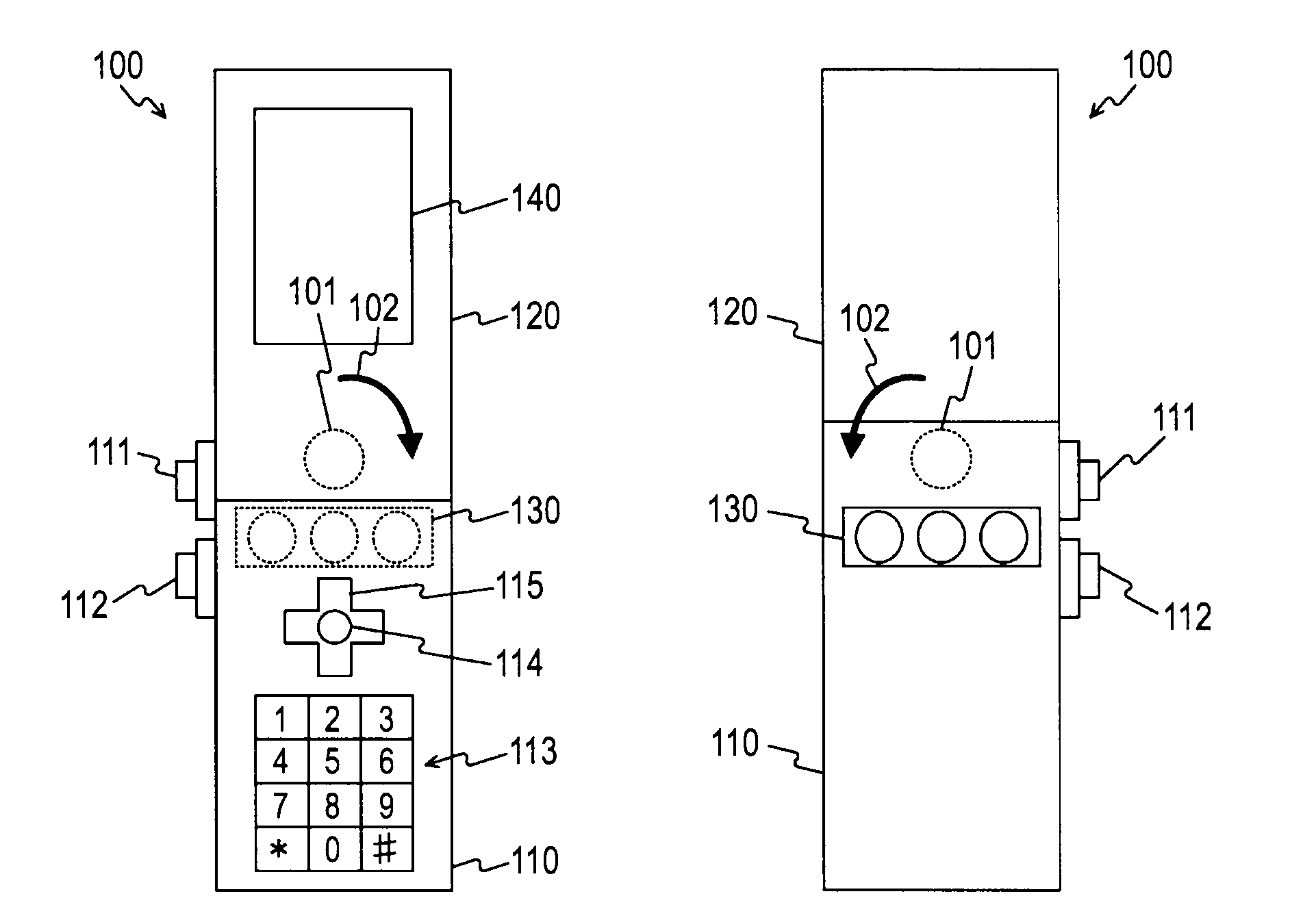
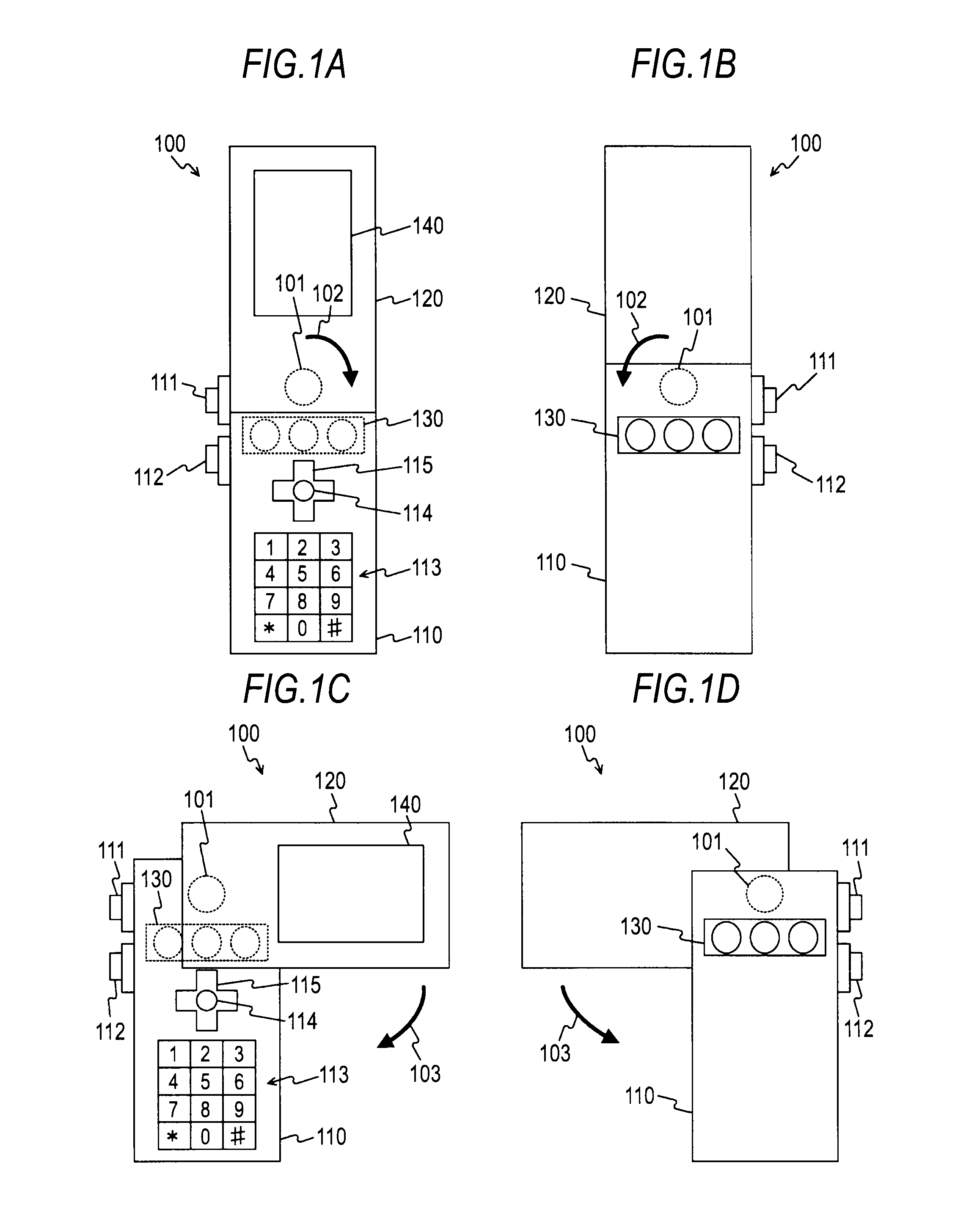
[0100]FIGS. 1A to 1D are diagrams of an external configuration example of a cellular phone apparatus 100 according to a first embodiment of the present invention. In FIG. 1A, a front side of a form in using the cellular phone apparatus 100 is shown. In FIG. 1B, a rear side of the form is shown. In FIG. 1C, a front side of another form in using the cellular phone apparatus 100 is shown. In FIG. 1D, a rear side of the form is shown.

[0101]The cellular phone apparatus 100 includes a first housing 110 and a second housing 120. The first housing 110 and the second housing 120 are pivotably coupled with a pivoting member 101 as a pivotal reference. The cellular phone apparatus 100 is realized by, for example, a cellular phone apparatus (so-called cellular phone apparatus with camera) having plural imaging functions. In FIGS. 1A to 1D, for ease of explanation, the cellular phone apparatus 100 is shown in a simplifi...

second embodiment

2. Second Embodiment

[0601]In the first embodiment, the cellular phone apparatus including the plural imaging systems is explained as an example. In a second embodiment of the present invention, an imaging apparatus such as a digital still camera or a digital video camera is explained.

[External Configuration Example of Imaging Apparatus]

[0602]FIGS. 72A to 72C are diagrams of the external configuration of an imaging apparatus 1000 in the second embodiment. In FIG. 72A, a perspective view of a front side (a subject side) of the imaging apparatus 1000 is shown. In FIGS. 72B and 72C, perspective views on a rear side (a photographer side) of the imaging apparatus 1000 are shown. In the imaging apparatus 1000, a first housing 1010 and a second housing 1020 are pivotably coupled by a pivoting member 1001. The imaging apparatus 1000 is realized by, for example, a digital still camera including three imaging systems. In FIGS. 72A to 72C, for easy of explanation, the imaging apparatus 1000 is ...


PUM


Abstract

An imaging apparatus includes: an imaging unit that respectively generates, with imaging devices different from one another, a first captured image with a specific direction of a subject set in a longitudinal direction, a second captured image with an orthogonal direction orthogonal to the specific direction set in a longitudinal direction and including a subject adjacent to one side of the orthogonal direction of the subject included in the first captured image, and a third captured image with the orthogonal direction set in a longitudinal direction and including a subject adjacent to the other side of the orthogonal direction of the subject included in the first captured image; a detecting unit that detects a state of the imaging apparatus; and a control unit that determines, based on the detected state, a range of a target image as a target of display or recording among the first to third captured images.

Description

BACKGROUND OF THE INVENTION[0001]1. Field of the Invention[0002]The present invention relates to an imaging apparatus and, more particularly, to an imaging apparatus including plural imaging systems, a method of controlling the imaging apparatus, and a computer program for causing a computer to execute the method.[0003]2. Description of the Related Art[0004]In recent years, an imaging apparatus such as a digital still camera or a digital video camera (e.g., a recorder integrated with a camera) including an imaging system that images a subject such as a person and configured to record, as an image file, an image generated by the imaging system (a captured image) is widespread.[0005]There is proposed an imaging apparatus including plural imaging systems and capable of generating a panorama image by combining images generated by the imaging system. For example, there is proposed an imaging apparatus including three imaging systems and configured to generate a panorama image by arrangin...

Claims


Application Information

Patent Timeline
Patent Type & Authority Patents(United States)
IPC IPC(8): H04N5/222H04N7/00H04N5/225H04N23/90
CPCH04N5/23238H04N5/378H04N5/3765H04N5/247H04N23/698H04N23/90H04N25/78H04N25/7795H04N25/75H04N25/745
Inventor ISHIDA, MINORU
Owner SONY SEMICON SOLUTIONS CORP
Learn More