Image pickup apparatus to control an exposure time based on motion of a detected optical image

a pickup apparatus and optical image technology, applied in exposure control, printing, instruments, etc., can solve the problems of degrading the image quality of a photographed image, degrading the image quality of a photograph, and affecting so as to reduce the image quality of hand shake or object shake, and improve the quality of the photograph. , the effect of easy photographing

Active Publication Date: 2014-05-27
PANASONIC CORP
View PDF75 Cites 2 Cited by
  • Summary
  • Abstract
  • Description
  • Claims
  • Application Information

AI Technical Summary

Benefits of technology

[0018]According to the present invention, it is possible to provide an image pick up apparatus whereby image quality degradation due to hand shake or object shake is reduced and whereby an image of high quality is easily photographed.

Problems solved by technology

However, together with the reductions in size and weight and escalation in the magnification of optical zooming of digital cameras, a blur may occur in photographed images and may degrade image quality thereof.
On the other hand, among causes for degrading the image quality of a photographed image is object shake caused by the motion of a shooting target in addition to camera shake caused by vibration such as hand shake added to the camera body.

Method used


Image

  • Image pickup apparatus to control an exposure time based on motion of a detected optical image
  • Image pickup apparatus to control an exposure time based on motion of a detected optical image
  • Image pickup apparatus to control an exposure time based on motion of a detected optical image

Examples


embodiment 1

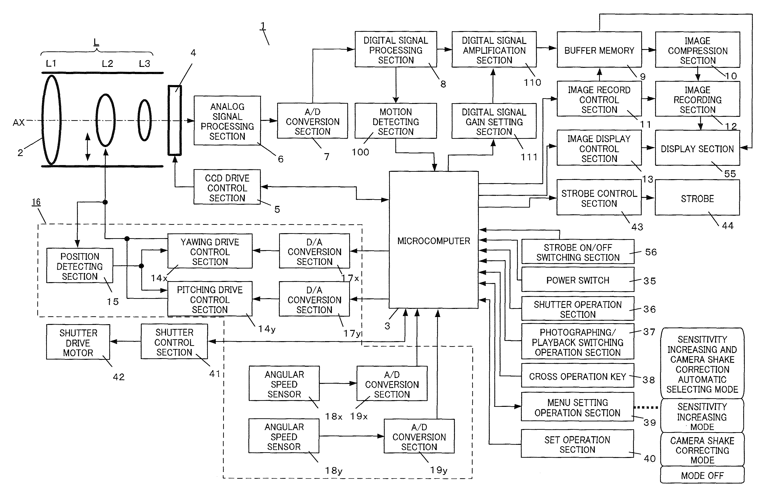
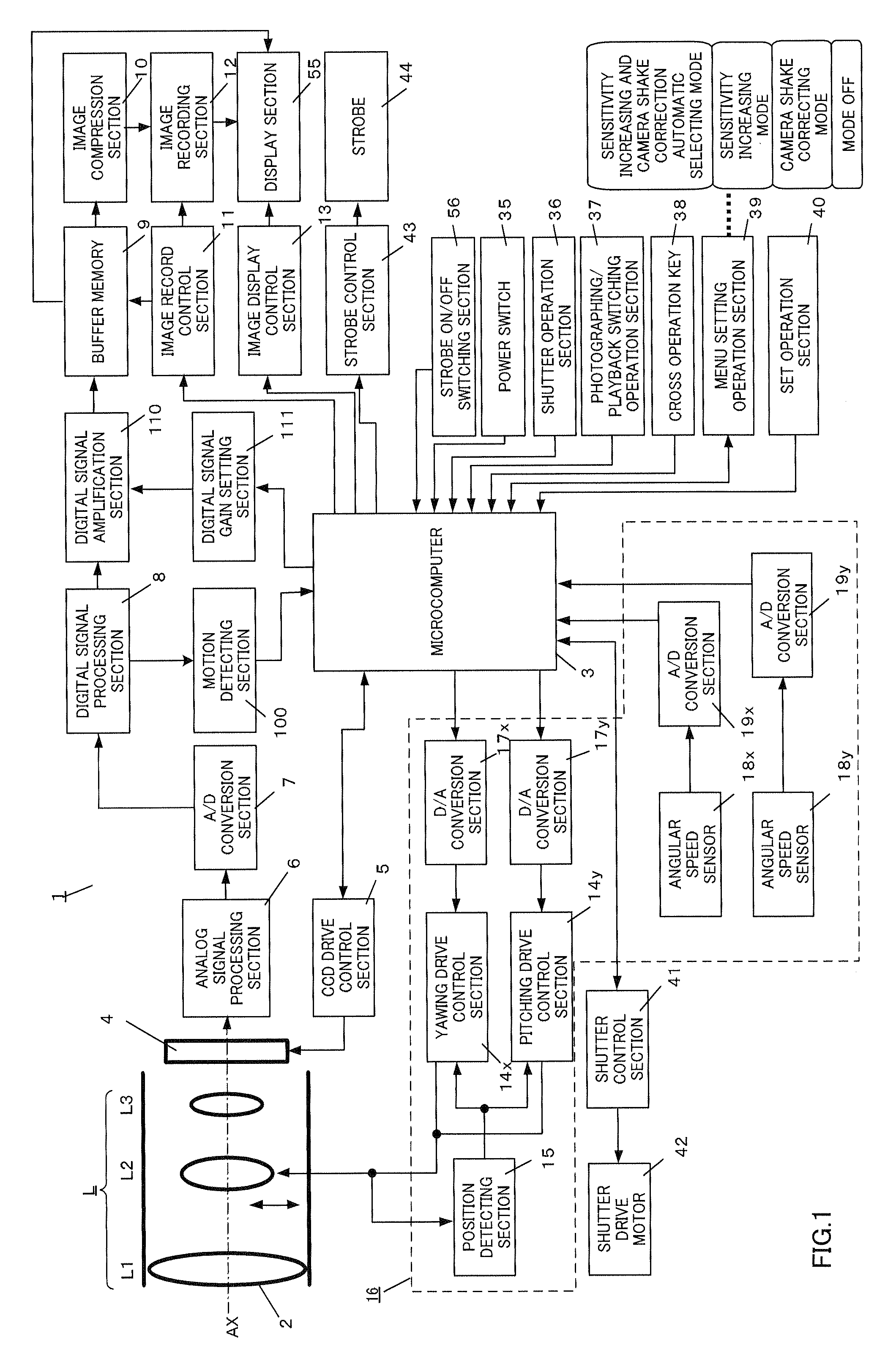
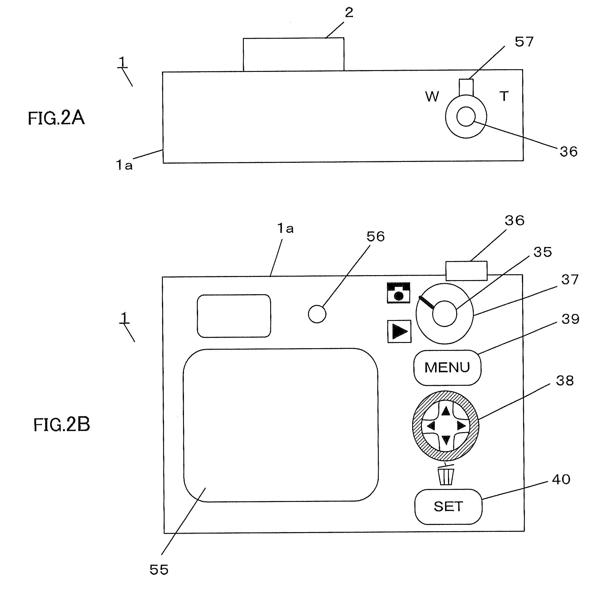
[0033]FIG. 1 is a block diagram showing the configuration of an image pickup apparatus according to an embodiment of the present invention. FIG. 2 illustrates the schematic configuration of the image pickup apparatus according to the present embodiment, where FIG. 2A shows a top view and FIG. 2B shows a rear view. The present embodiment is an example where the present invention is applied to a digital camera having a camera shake correcting function and a photographing sensitivity change function. In the following explanation, the “moving speed” of a photographing object (also referred to as “object speed”) is the moving speed of the optical image of the photographing object on the image pickup plane, caused by one of or both of camera shake and object shake.

[0034]In FIG. 1, digital camera 1 employs a configuration having image pickup optical system L, microcomputer 3, image pickup sensor 4, CCD (Charge Coupled Device) drive control section 5, analog signal processing section 6, A / D...

embodiment 2

[0087]Next, the digital camera according to Embodiment 2 will be explained. Although the digital camera according to the present embodiment has a similar basic configuration to the digital camera according to Embodiment 1, the digital camera differs in that a panning shot mode is further selectable as an photographing mode. Here, “panning shot” is a method whereby, when a fast moving photographing object is photographed, a photograph is taken by pressing shutter operation section 36 while the orientation of the camera is moved in the traveling direction, and it is possible to take a photograph by taking a photograph in the panning shot mode as if the photographing object is still and the background is flowing. In the present embodiment, the same components as those of Embodiment 1 are assigned the same reference numerals and explanations will be focused on differences from Embodiment 1.

[0088]FIG. 7 is a flowchart showing photographing processing of the digital camera according to Em...

embodiment 3

[0095]Next, the digital camera according to Embodiment 3 will be explained. Although the digital camera according to the present embodiment has a similar basic configuration to the digital configuration described in Embodiments 1 and 2, the digital camera differs in that photographing sensitivity is set according to the moving speed of the photographing object. Explanations will be focused on points different from Embodiments 1 and 2 below.

[0096]When the photographer presses shutter operation section 36 halfway, motion detecting section 100 detects the motion of the photographing object and outputs a detecting vector. Microcomputer 3 calculates moving speed Vh of the photographing object from the outputted detecting vector. Moreover, microcomputer 3 calculates the shutter speed at which no object shake occurs from moving speed Vh and sets photographing sensitivity where photographing can be taken at the calculated shutter speed. For example, when a photographing object moving slowly...


PUM


Abstract

Provided is an imaging device capable of reducing image degradation due to a shake of a hand or an object and easily capturing an image of preferable image quality. The imaging device (1) includes: an imaging optical system (L) for forming an optical image of an object; an imaging sensor (4) for receiving the formed optical image and converting it into an electric image signal for output; a motion detecting unit (100) for detecting a motion of an object to be imaged according to the outputted image signal; and a microcomputer (3) for controlling an exposure time in accordance with the motion of the detected optical image of the object.

Description

TECHNICAL FIELD[0001]The present invention relates to an image pickup apparatus and a lens barrel. More particularly, the present invention relates to an image pickup apparatus and a lens barrel having a camera shake correcting function and a photographing sensitivity change function.BACKGROUND ART[0002]Image pickup apparatuses such as a digital still camera and digital video camera capable of converting an optical image of a photographing object to an electrical image signal and outputting the image signal (hereinafter simply “digital camera”) are rapidly becoming widespread. With reductions in size and weight and escalation in the magnification of optical zooming in recent years in particular, digital cameras are significantly becoming convenient for photographers.[0003]However, together with the reductions in size and weight and escalation in the magnification of optical zooming of digital cameras, a blur may occur in photographed images and may degrade image quality thereof.[000...

Claims


Application Information

Patent Timeline
Patent Type & Authority Patents(United States)
IPC IPC(8): G03B17/00H04N5/232H04N5/228
CPCH04N5/23258H04N5/2328H04N5/23261H04N5/23248H04N5/23254G03B5/02H04N23/6811H04N23/68H04N23/6815H04N23/685H04N23/6812
Inventor YUMIKI, NAOTO
Owner PANASONIC CORP
Why Eureka
Try Eureka