
Imaging apparatus, image processing apparatus, image processing method, and program

a technology of image processing and image processing, applied in the field of image processing apparatus, can solve the problems of reduced faces of respective persons included in the panoramic image, difficulty in viewing the appearance, appearance, and the like of the respective faces, and achieve the effect of excellent

Inactive Publication Date: 2014-10-07
SONY CORP
View PDF6 Cites 3 Cited by
  • Summary
  • Abstract
  • Description
  • Claims
  • Application Information

AI Technical Summary

Benefits of technology

The technique described in this patent allows for easy capture of panoramic images, including multiple people in front of a famous building. The photographed images can be displayed on a screen for immediate viewing. The invention allows for effective representation of the captured image based on its type.

Problems solved by technology

Therefore, the faces of the respective persons included in the panoramic image are also reduced, and it is difficult to view the looks, appearance, and the like of the respective faces.

Method used


Image

  • Imaging apparatus, image processing apparatus, image processing method, and program
  • Imaging apparatus, image processing apparatus, image processing method, and program
  • Imaging apparatus, image processing apparatus, image processing method, and program

Examples


first embodiment

1. First Embodiment

External Configuration Example of Mobile Phone Unit

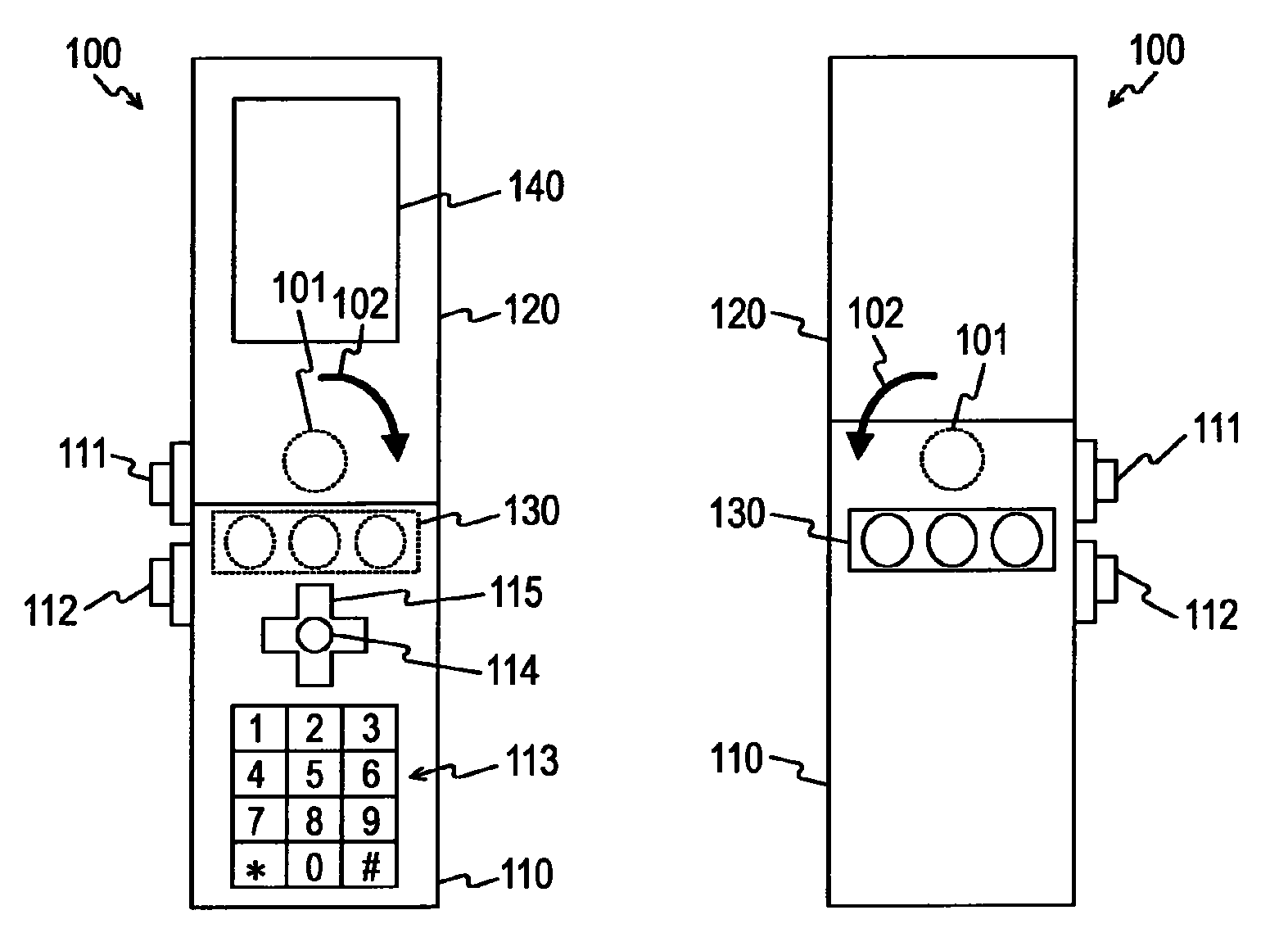
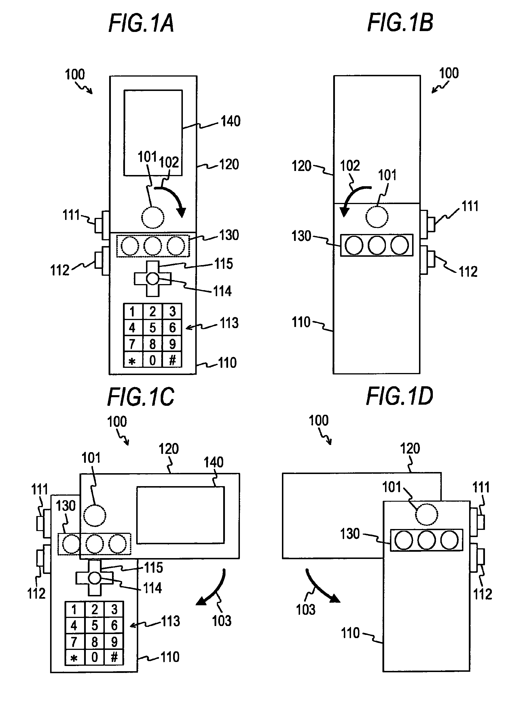
[0129]FIGS. 1A to 1D are diagrams showing an external configuration example of a mobile phone unit 100 according to a first embodiment of the present invention. FIG. 1A shows a front surface side in one state of using the mobile phone unit 100 and FIG. 1B shows a rear surface side in the same state. FIG. 1C shows a front surface side in another state of using the mobile phone unit 100 and FIG. 1D shows a rear surface side in the same state.

[0130]The mobile phone unit 100 includes a first casing 110 and a second casing 120. The first and second casings 110 and 120 are connected so as to be rotatable about a pivot member 101. The mobile phone unit 100 is realized by a plurality of mobile phone units (so-called camera-equipped mobile phone units) having imaging capability, for example. FIGS. 1A to 1D show a simplified view of the mobile phone unit 100 in order to make the description easily understood, and the illust...

second embodiment

2. Second Embodiment

[0770]In the first embodiment of the present invention, an example in which when displaying a postview image, a captured image and an enlarged image of a part thereof are displayed in a correlated manner has been described. Here, for example, the enlarged image of the panoramic image is an image included in a partial region of the panoramic image. Therefore, for example, when the enlarged image is displayed, the user may want to display the surrounding image of the enlarged image of the panoramic image. In such a case, it is possible to display the enlarged image of a desired region by moving a display target region of the enlarged image with the user operation. However, since the panoramic image is long in a specific direction (for example, the horizontal direction), when the enlarged image being displayed presently is the central portion of the panoramic image, and the desired region is the end portion in the specific direction, it is expected that the user has...


PUM


Abstract

An imaging apparatus includes: an image generation section that generates at least one of a first captured image having a predetermined size and a second captured image having an aspect ratio different from that of the first captured image; a recording control section that, when an instruction operation to record the generated captured image is received, records the generated captured image based on the instruction operation; and a display control section that, when a captured image to be displayed at the time of displaying the recorded captured image on a display section is the second captured image, displays the second captured image and an enlarged image of a specific region in the second captured image are displayed on the display section in a correlated manner.

Description

BACKGROUND OF THE INVENTION[0001]1. Field of the Invention[0002]The present invention relates to an imaging apparatus, and more particularly, to an imaging apparatus for displaying images, an image processing apparatus, a processing method in these apparatuses, and a program for causing a computer to execute the method.[0003]2. Description of the Related Art[0004]In recent years, imaging apparatuses such as digital still cameras or digital video cameras (for example, camcorders) which include an imaging system for imaging a subject such as a person and which record images (captured images) generated by the imaging system as image files have become popularized.[0005]Moreover, imaging apparatuses capable of generating an image (for example, a panoramic image) in which an imaging range is relatively widened in a particular direction by combining a plurality of captured images together have been proposed. For example, an imaging apparatus which includes three imaging systems and which g...

Claims


Application Information

Patent Timeline
Patent Type & Authority Patents(United States)
IPC IPC(8): H04N5/76H04N5/222H04N5/225
CPCH04N5/225H04M2250/52H04N5/23238H04N23/95H04N23/698H04N23/00
Inventor ISHIDA, MINORU
Owner SONY CORP
Learn More