Drive arrangement and process for the drive of an agricultural implement

a technology of agricultural implements and drive lines, applied in agricultural machines, analogue processes for specific applications, instruments, etc., can solve problems such as time-consuming, inconvenient and uncomfortable, and overloading of drive lines

Active Publication Date: 2013-11-05
DEERE & CO
View PDF14 Cites 11 Cited by
  • Summary
  • Abstract
  • Description
  • Claims
  • Application Information

AI Technical Summary

Benefits of technology

[0008]In this way the cut-off of the power take-off shaft occurs at a torque at which the overload clutch of the drive line of the operating implement has not yet responded. Accordingly the driven elements of the operating implement are not yet overloaded during the cut-off of the power take-off shaft output that would cut-off the overload clutch. The second attempt at the removal of the cause of the overload, for example of a jam of the elements of the harvested crop take up arrangement for the take up of the harvested crop, is performed at a higher attainable torque than in the normal operation, which is also greater than the cut-off torque of the overload clutch. During the subsequent return to operation of the power take-off shaft output the cause of the overload can therefore usually be reduced by the driven elements of the operating implements. Thereby, an effective security of the drive line of operating implements is attained by simple means and the cause of a possible overload can be removed.

Problems solved by technology

In agricultural operating implements there is the danger that damage to the drive line or to driven components can occur due to overloads.
For example, in the case of balers or towed forage harvesters, a blockage or stoppage of the elements that take up or convey the harvested crop, which in turn can overload the drive line.
Other examples are rotating ground breaking implements that become overloaded at excessive operating depths or heavy ground conditions, or mowing implements, that are stalled by excessively heavy plant components.
The process described here is time consuming, inconvenient and uncomfortable.
The disadvantage here is seen in the relatively high cost of the safety clutches with their variable cut-off torque.

Method used


Image

  • Drive arrangement and process for the drive of an agricultural implement
  • Drive arrangement and process for the drive of an agricultural implement
  • Drive arrangement and process for the drive of an agricultural implement

Examples


Embodiment Construction

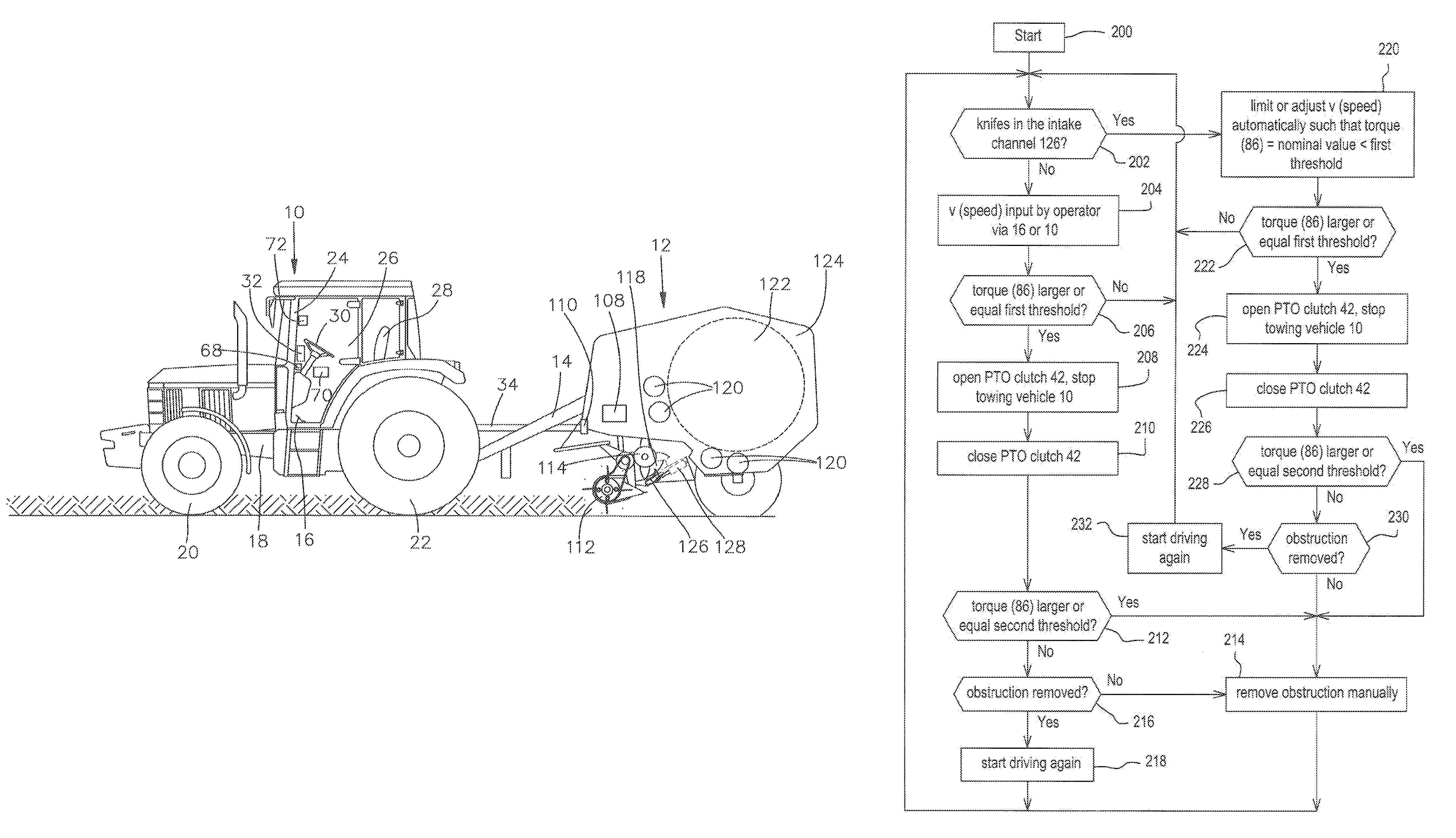
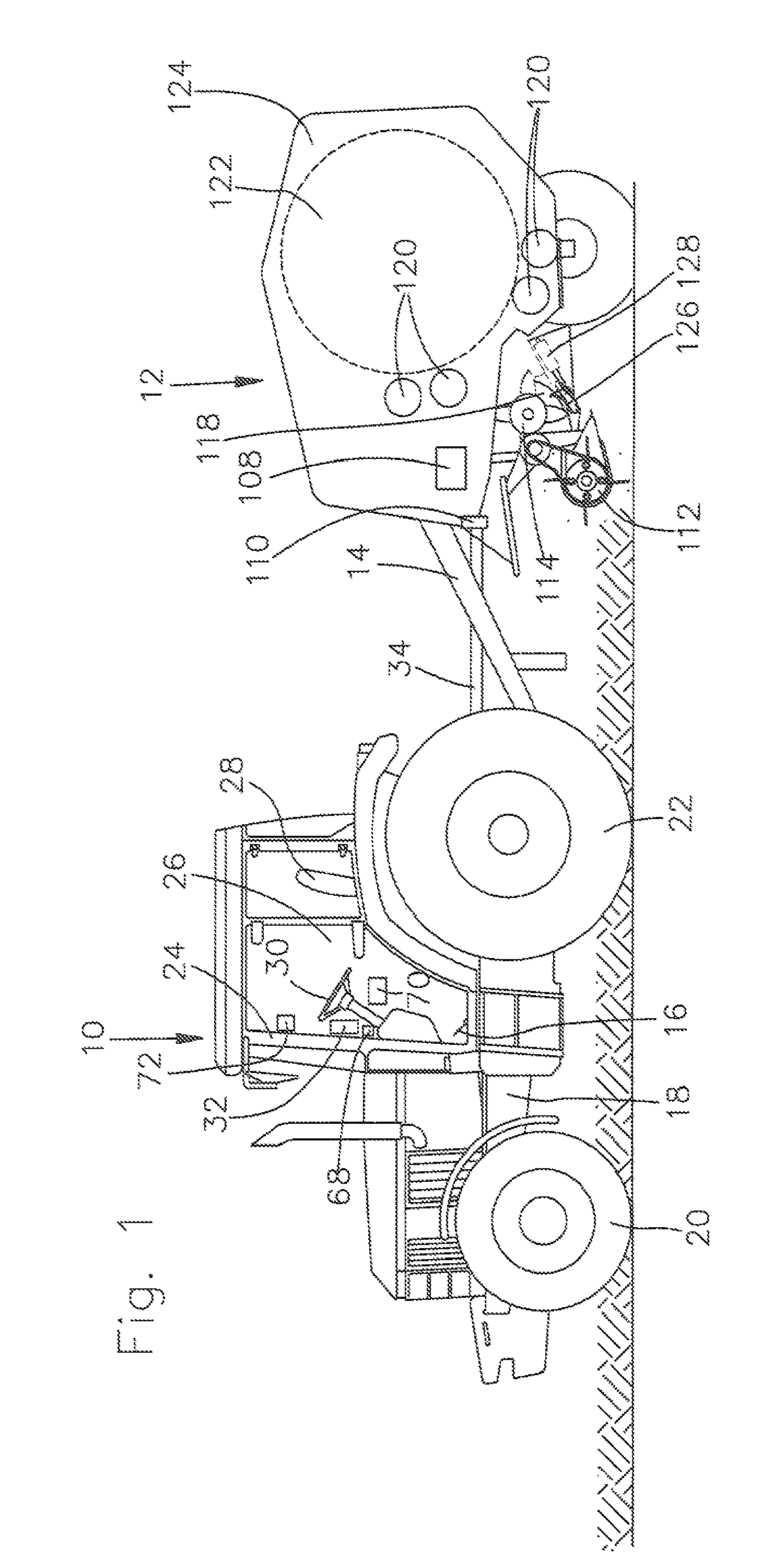
[0019]FIG. 1 shows a side view of an agricultural towing vehicle 10 in the form of a tractor and an operating implement coupled by means of a towbar 14 to an attachment coupling (not shown) of the towing vehicle 10. The operating implement is shown in the form of a round baler 12, known in itself, with a variable size baling chamber (see EP 0 316 506 A). The towing vehicle 10 is supported on a carrying frame 18 that is supported on steerable front wheels 20 and driven rear wheels 22 and carries a cab 24 which includes an operator's station 26.

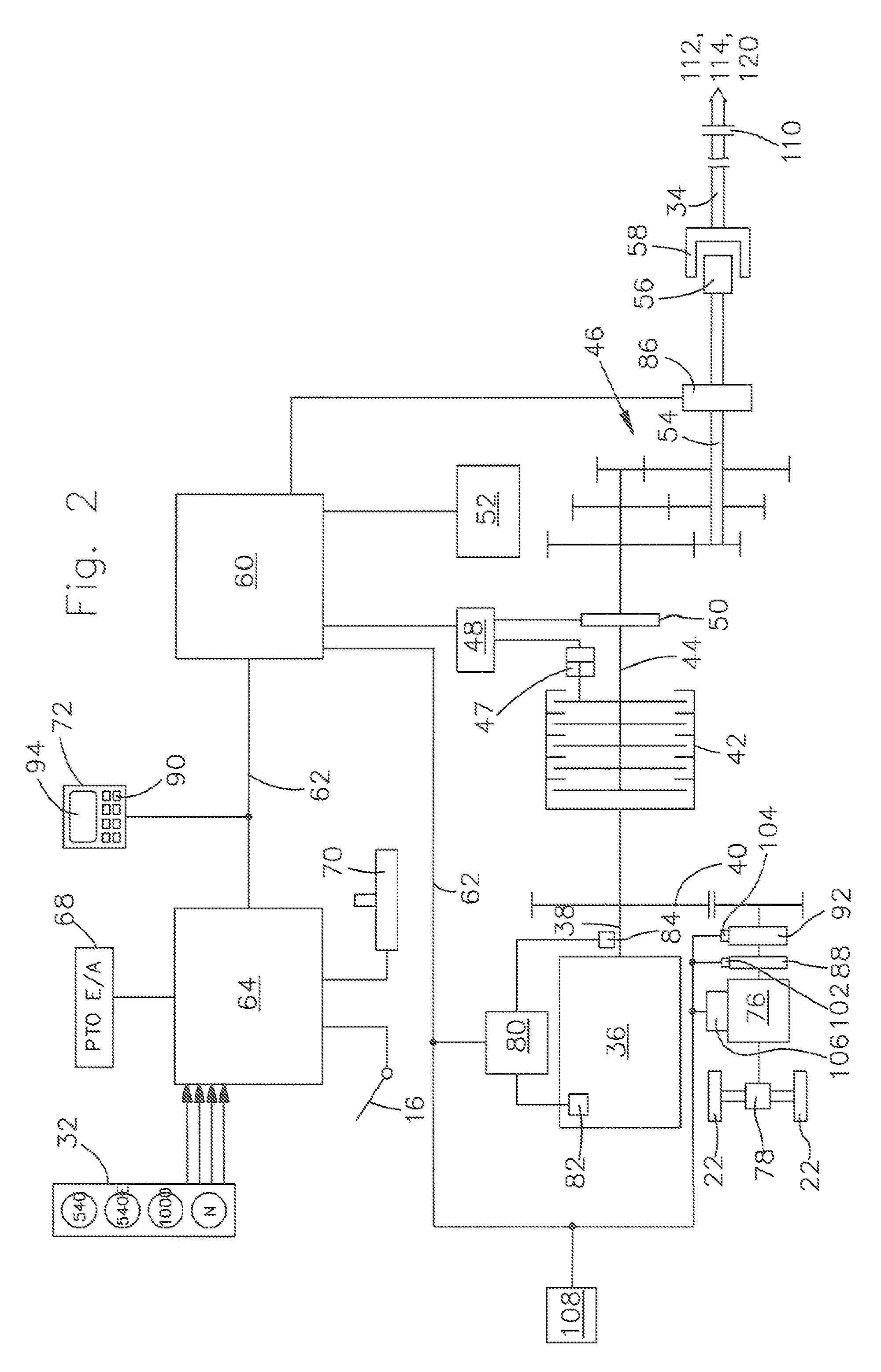
[0020]The operator's station 26 includes a seat 28, a steering wheel 30, a gas pedal 16 and other pedals for brakes and clutch (not shown) and several input elements arranged within the reach of an operator located at the operator's station 26 for the input of functions of the operating implement 10 that can be selected. The latter is coupled to a selector arrangement 32 for the gear ratio of a power take-off shaft drive 46, a manual throttle l...


PUM


Abstract

A drive arrangement for the drive of an agricultural implement is provided that includes a drive engine that can be brought into a drive connection over a separable power take-off shaft clutch with a power take-off shaft output. A drive line of the operating implement is connected with the power take-off shaft output, with an overload clutch, and a control arrangement. The control arrangement is connected to a sensor arranged for the detection of the torque at the power take-off shaft output and, in normal operation, permits an actuator to disengage the power take-off shaft clutch as soon as the torque detected by the sensor reaches or exceeds a first threshold value, that corresponds to a torque that is smaller than the cut-off torque of the overload clutch. Immediately following, the control arrangement orders the actuator to engage the power take-off shaft clutch and when the power take-off shaft clutch is disengaged permits a torque at the power take-off shaft output that is greater than the cut-off torque of the overload clutch.

Description

FIELD OF THE INVENTION[0001]The invention concerns an arrangement and process for the drive of an agricultural implement. The drive includes a drive engine, that is connected so as to drive a separable power take-off shaft output over a power take-off shaft clutch. A drive line of the operating implement is connected to the power take-off shaft output that includes an overload clutch that interrupts the drive line when a cut-off torque is exceeded. A control arrangement is connected to a sensor arranged to detect the torque at the power take-off shaft output, that is arranged to operate an actuator to disengage the power take-off shaft clutch as soon as the torque detected by the sensor reaches or exceeds a predetermined threshold value.BACKGROUND OF THE INVENTION[0002]In agricultural operating implements there is the danger that damage to the drive line or to driven components can occur due to overloads. For example, in the case of balers or towed forage harvesters, a blockage or s...

Claims


Application Information

Patent Timeline
Patent Type & Authority Patents(United States)
IPC IPC(8): G06F7/70
CPCA01B61/025A01D69/002A01D90/14A01F15/0841A01D75/182
Inventor HEL, SÉBASTIENBIZIOREK, STÉPHANE
Owner DEERE & CO
Why Eureka
Try Eureka