System and method for reducing effect of magnetic fields on a magnetic transducer

Active Publication Date: 2005-01-06
MED EL ELEKTROMEDIZINISCHE GERAETE GMBH
View PDF15 Cites 68 Cited by
  • Summary
  • Abstract
  • Description
  • Claims
  • Application Information

AI Technical Summary

Benefits of technology

[0021] In further embodiments related to the above-described embodiments, the magnet(s) and/or the inner wall of the housing may be coated with a material providing low friction, such as Teflon®. The friction of the magnet(s) may be reduced by lubricants. The housing may be hermetically sealed and may be adapted to be fixed to an ossicle. The at least one coil may be positioned within, or external to, the housing. The electro-magnetic transducer may include more than one external coil

Problems solved by technology

Due to the external magnetic field, the implanted magnet becomes partly demagnetized and this may lead to damage or at least to a reduced power efficiency of the electromagnetic transducer after exposure to the M

Method used


Image

  • System and method for reducing effect of magnetic fields on a magnetic transducer
  • System and method for reducing effect of magnetic fields on a magnetic transducer
  • System and method for reducing effect of magnetic fields on a magnetic transducer

Examples


Embodiment Construction

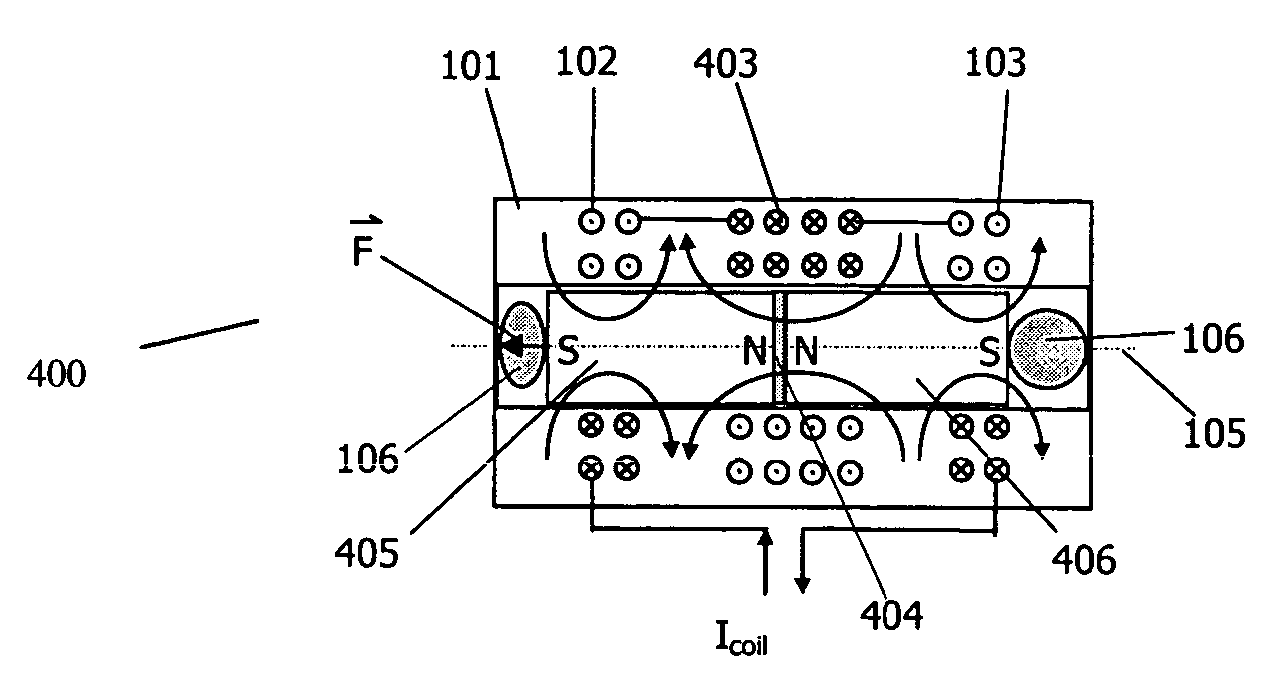
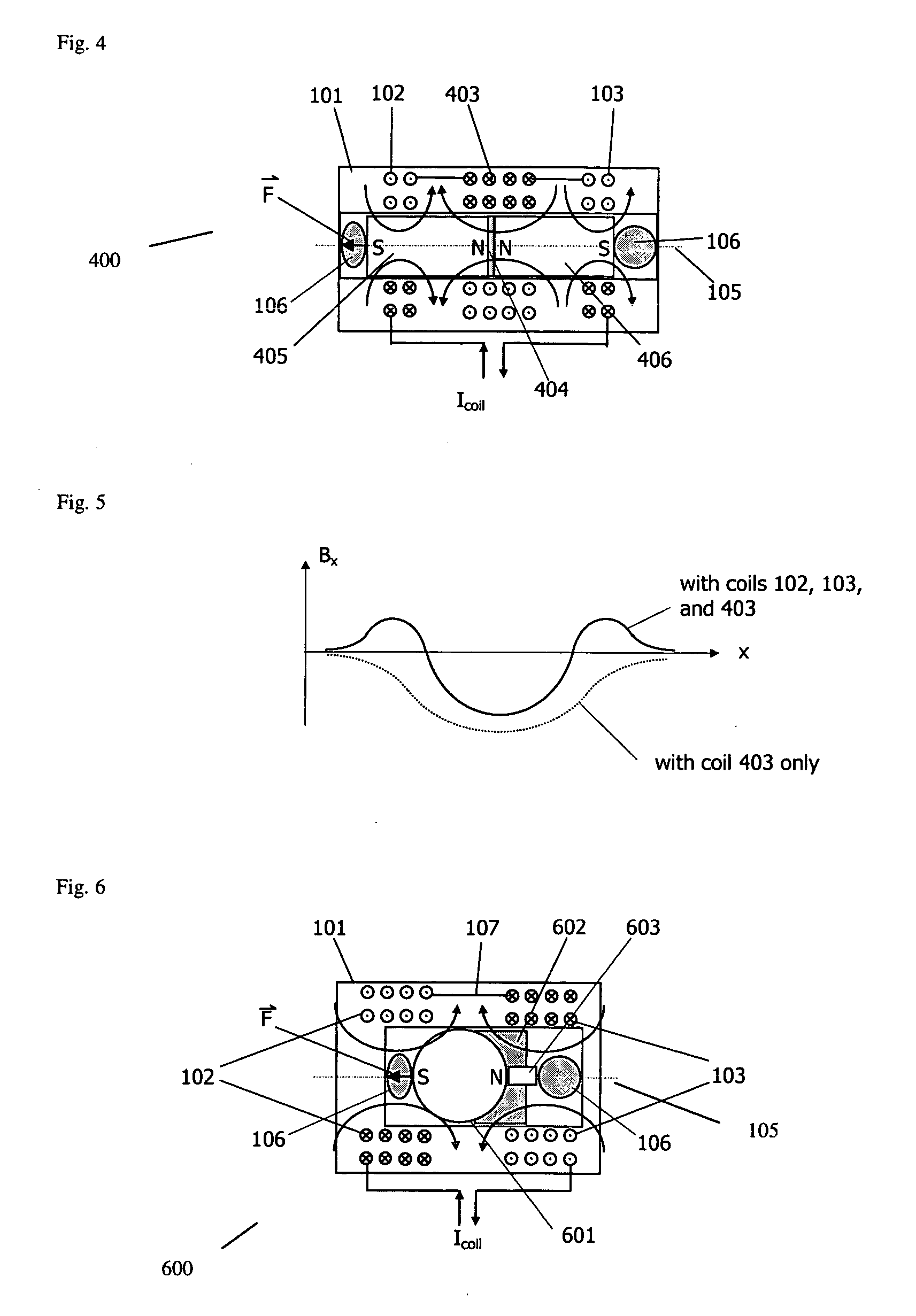
[0040] In illustrative embodiments, an electromagnetic transducer is presented that advantageously reduces the effect of external magnetic fields. The transducer is generally free of torque in the presence of an external magnetic field of any direction and orientation. Moreover, in various embodiments, the transducer resists de-magnetization and is safe against induction of voltages arising from magnetic pulses that may occur, for example, during Magnetic Resonance Imaging (MRI).

[0041]FIG. 4 shows a transducer 400 acting as a mechanical stimulator in accordance with one embodiment of the invention. As used in this description, and the accompanying claims, the term “transducer” as used herein shall mean a device that converts energy or information of one physical quantity into another physical quantity. A transducer may act as a sensor and / or a stimulator / driver, as known in the art.

[0042] The transducer 400 includes a housing 101, which in preferred embodiment is non-ferromagnetic...


PUM


Abstract

An electromagnetic driver transducer free of torque in the presence of an external magnetic field, of any direction and orientation (such as in a Magnetic Resonance Imaging environment). The transducer includes a housing. At least one coil is associated with the housing. A plurality of magnets within the housing are aligned along an axis in an anti-parallel orientation. The magnets are free to move along an axis, wherein vibration of the magnets causes vibration of the housing. The transducer may be, for example, fixed to an ossicle.

Description

CROSS REFERENCE TO RELATED APPLICATIONS [0001] The present application claims priority from U.S. provisional application Ser. No. 60 / 482,687, entitled “Reducing Effect of Magnetic Fields on a Magnetic Transducer,” filed Jun. 26, 2003. This application is also a continuation-in-part of U.S. patent application Ser. No. 10 / 405,093, filed Apr. 1, 2003, entitled “Reducing Effects of Magnetic and Electromagnetic Fields on an Implant's Magnet And / Or Electronics,” which claims priority from U.S. provisional application number Ser. No. 60 / 369, 208, filed Apr. 1, 2002 and from U.S. provisional application No. 60 / 387,455, filed Jun. 10, 2002. Each of the above-mentioned applications is hereby incorporated herein by reference.TECHNICAL FIELD [0002] The present invention relates to transducers and external magnetic fields, and more particularly to an apparatus and method for reducing the effect of external magnetic fields on an electromagnetic transducer which may be positioned, for example, wit...

Claims


Application Information

Patent Timeline
IPC IPC(8): H04R25/00
CPCB06B1/045H01H36/0073H04R25/606H02K35/02H04R11/00H02K33/16
Inventor ZIMMERLING, MARTIN
Owner MED EL ELEKTROMEDIZINISCHE GERAETE GMBH
Why Eureka
Try Eureka