Electric zero-turn working vehicle

a technology of working vehicle and electric motor, which is applied in the direction of vehicle components, non-deflectable wheel steering, agriculture tools and machines, etc., can solve the problems of increasing the capacity of the pto electric motor to cover the power loss, affecting the balance of the vehicle, and affecting the safety of workers, etc., to achieve the effect of free from poor balance and/or power loss

Active Publication Date: 2013-11-12
KANZAKI KOKYUKOKI MFG
View PDF10 Cites 28 Cited by
  • Summary
  • Abstract
  • Description
  • Claims
  • Application Information

AI Technical Summary

Benefits of technology

[0008]An object of the invention is to provide an electric zero-turn working vehicle that is free from poor balance and / or power loss caused by a wrong arrangement of an electric motor for driving a working implement.

Problems solved by technology

Here, a problem arises that a relatively heavy PTO electric motor for driving a working implement may adversely affect the balance of the vehicle if the PTO electric motor is disposed adjacent to the working implement, such as a mower unit, that is distant from the right and left transaxles adjacent to the right and left drive wheels.
On the contrary, if the PTO electric motor is distant from a working implement, for example, if the PTO electric motor is disposed above one of front and rear portions of a vehicle body frame, and a mower unit serving as the working implement is disposed below the other of front and rear portions of the vehicle body frame, loss of power transmitted from the PTO electric motor to the working implement may increase or the PTO electric motor may have to increase its capacity for covering the power loss.

Method used


Image

  • Electric zero-turn working vehicle
  • Electric zero-turn working vehicle
  • Electric zero-turn working vehicle

Examples


embodiment 1

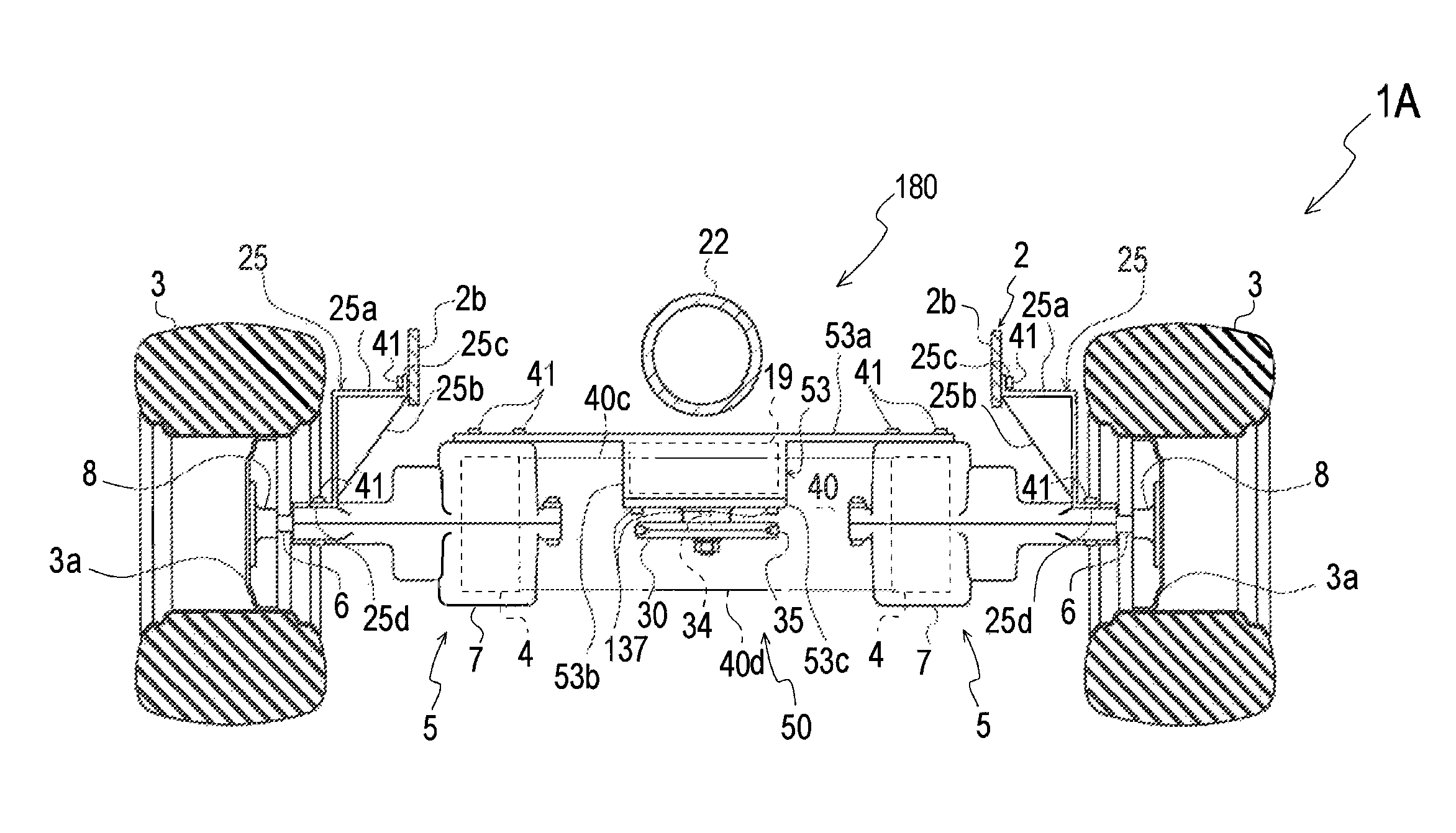
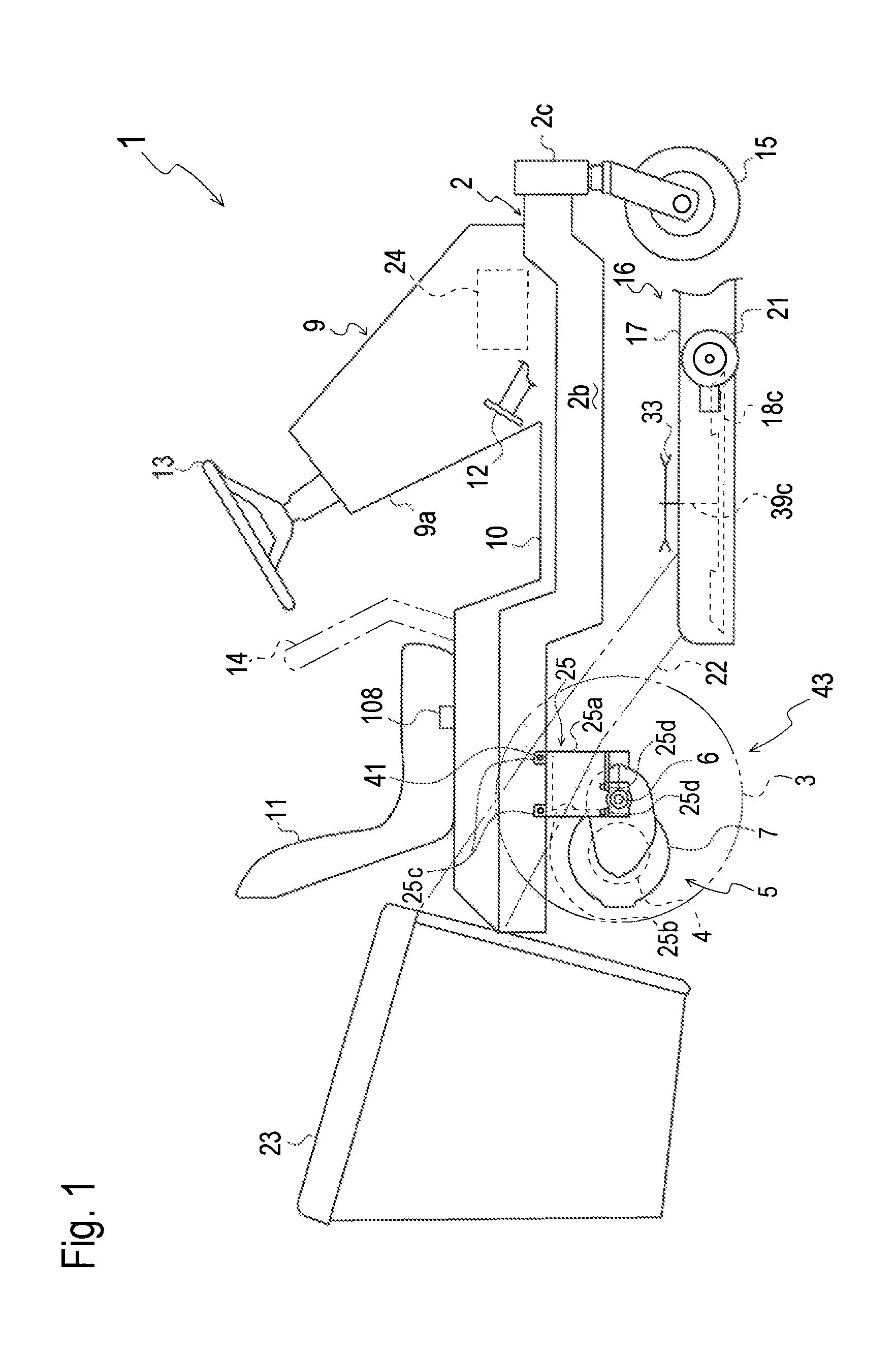
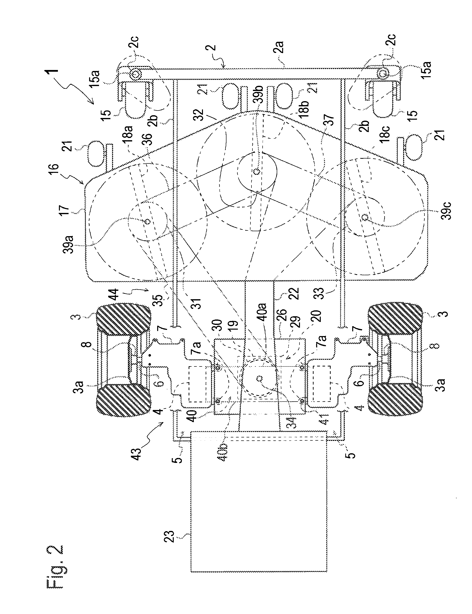
[0071]A lawn mower 1 serving as an electric zero-turn working vehicle will be described with reference to FIGS. 1 to 3. Lawn mower 1 includes a vehicle body frame 2, and right and left drive wheels 3 are disposed on right and left outsides of a rear portion of vehicle body frame 2, respectively, so as to serve as right and left rear wheels of lawn mower 1. Right and left transaxles 5 are supported by the rear portion of vehicle body frame 2 and are disposed below vehicle body frame 2. Right and left transaxles 5 include respective right and left traveling electric motors 4 for driving respective right and left drive wheels 3. Right and left transaxles 5 and right and left drive wheels 3 are assembled into a rear-wheel driving assembly 43 as detailed later.

[0072]Right and left transaxles 5 include respective right and left transaxle casings 7 each of which incorporates corresponding traveling electric motor 4 and a reduction gear train 67 (see FIG. 8 regarding another later-discusse...

embodiment 3

[0140]Referring to FIGS. 7 to 11, an electric zero-turn working vehicle according to an embodiment 3 is provided with a transaxle having a single transaxle casing supporting both axles of right and left drive wheels. Right and left traveling electric motors for driving the respective right and left axles and a PTO electric motor for driving a working implement are disposed in the transaxle casing, thereby reducing the number of parts.

[0141]Lawn mower 1D serving as an electric zero-turn working vehicle according to embodiment 3 will be described with reference to FIGS. 7 to 9. Lawn mower 1D is provided with a transaxle 46 for driving right and left drive wheels 3. Transaxle 46 includes a single transaxle casing 47 supporting right and left axles 6 of respective right and left drive wheels 3. Transaxle casing 47 incorporates right and left traveling electric motors 4 and PTO electric motor 19. Therefore, transaxle 46 with right and left drive wheels 3 serves as aforesaid rear-wheel dr...


PUM


Abstract

An electric zero-turn working vehicle comprises a vehicle body frame, right and left drive wheels, right and left first electric motors for driving the respective right and left drive wheels, a transaxle including at least one of the right and left first electric motors, a working implement, and a second electric motor for driving the working implement. The right and left first electric motors have a space therebetween. The transaxle is supported by the vehicle body frame and is disposed below the vehicle body frame. At least a part of the second electric motor is disposed in the space between the right and left first electric motors.

Description

BACKGROUND OF THE INVENTION[0001]1. Field of the Invention[0002]The present invention relates to an electric zero-turn working vehicle, such as a lawn mower, equipped with a pair of right and left electric motors for driving respective right and left drive wheels, and equipped with an electric motor for driving a working implement, such a mower unit.[0003]2. Background Art[0004]An electric tractor disclosed by JP 2002-356116 A, serving as a typical electric working vehicle, is equipped with a battery, a traveling electric motor, and a PTO (power take-off) electric motor. The traveling electric motor is supplied with electric power from the battery to drive right and left drive wheels. The PTO electric motor is also supplied electric power from the battery to drive a PTO shaft for driving a working implement. The electric tractor is advantageously lightened because the battery, the traveling electric motor and the PTO electric motor are light in comparison with an engine and implemen...

Claims


Application Information

Patent Timeline
Patent Type & Authority Patents(United States)
IPC IPC(8): B62D11/04
CPCA01D69/02A01D34/78
Inventor SASAHARA, KENGOKOGA, KAZUNARIITOU, MASAYA
Owner KANZAKI KOKYUKOKI MFG
Why Eureka
Try Eureka