Terminal supporting device

a technology of supporting device and terminal, which is applied in the direction of electrical equipment, etc., can solve the problems of difficulty in performing difficult operations, complicated structure or operation of preventing the looseness of the cylindrical nut member b>103/b>, etc., and achieve the effect of simple configuration and quick and easy fixing of the operation of the cable terminal

Active Publication Date: 2013-11-12
HI-LEX CORPORATION
View PDF5 Cites 0 Cited by
  • Summary
  • Abstract
  • Description
  • Claims
  • Application Information

AI Technical Summary

Benefits of technology

[0007]It is an object of the present invention to provide a terminal supporting device which a fixing operation of a cable terminal can be performed quickly and easily with a simple configuration.
[0009]In this terminal supporting device, it is preferable that the fitting projection is positioned between one end and the other end in a periphery direction of the main body, because the oscillation due to the vibration can be prevented thereby and the gradual rise of the stopper is further prevented. Even in the case where the both ends of the lock body in the periphery direction are sandwiched with members for sliding which controls a detaching direction, it is necessary to provide a space between the lock body and the members for sliding such that the members for sliding can slide easily. Therefore, the fitting projection can further prevent the gradual rise of the stopper.
[0013]According to the terminal supporting device of the present invention, it is possible that a fixing operation of a cable terminal is performed quickly and easily with a simple configuration.

Problems solved by technology

However, there is a problem that the structure or operation for preventing the looseness of the cylindrical nut member 103 becomes complicated.
Therefore, some operators might be forced to perform a difficult operation due to the strong bias of the coil spring 105.

Method used


Image

  • Terminal supporting device
  • Terminal supporting device
  • Terminal supporting device

Examples


Embodiment Construction

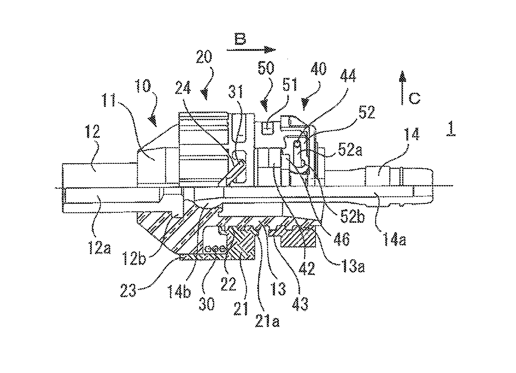
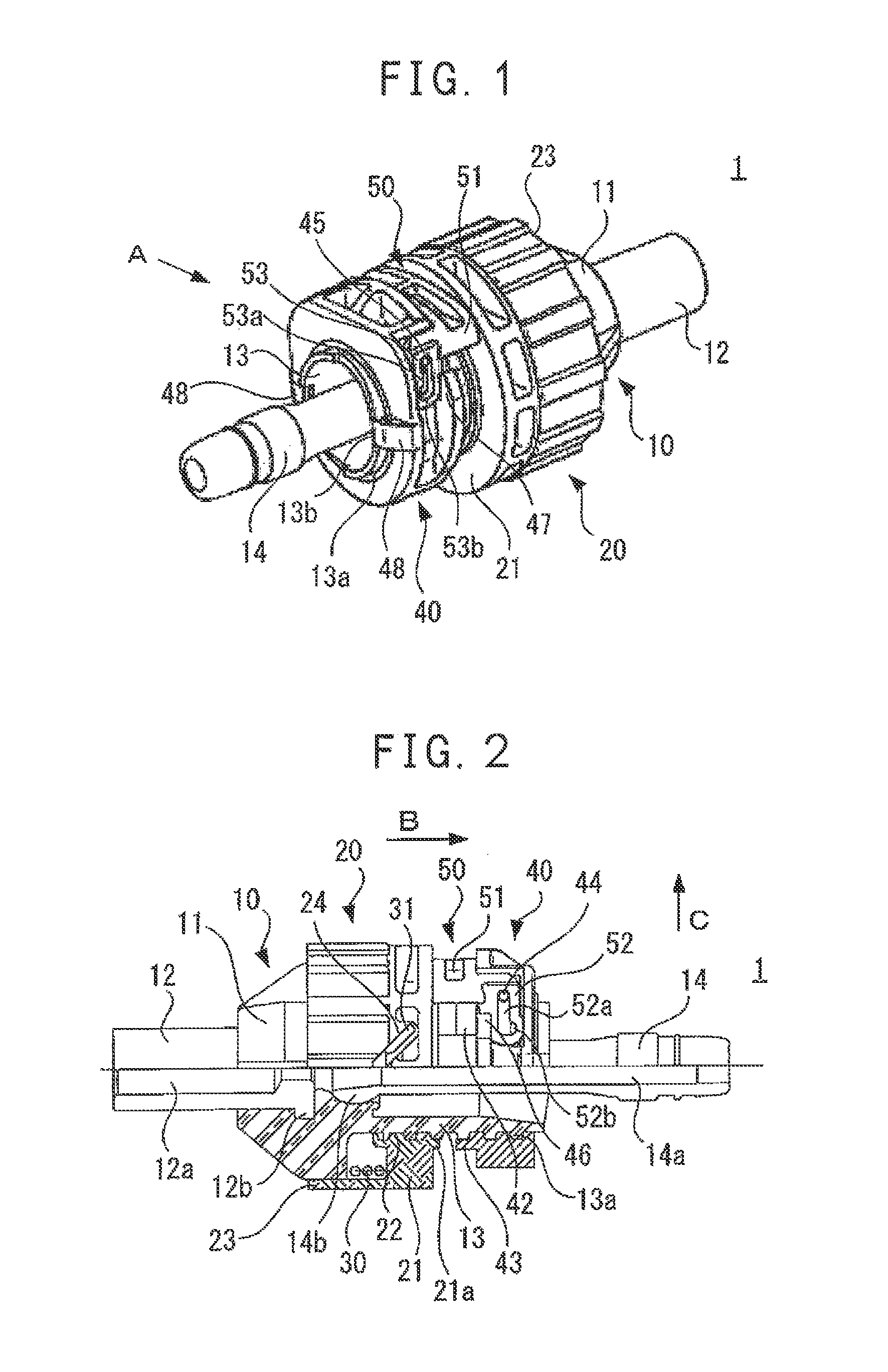
[0023]Hereinafter, embodiments of the present invention will be explained with reference to the accompanying drawings. FIG. 1 is a perspective view of a terminal supporting device according to one embodiment of the present invention, and FIG. 2 is a side view of the device of FIG. 1 in a direction of arrow A. In FIG. 2, the bottom half of the figure is shown as a sectional view.

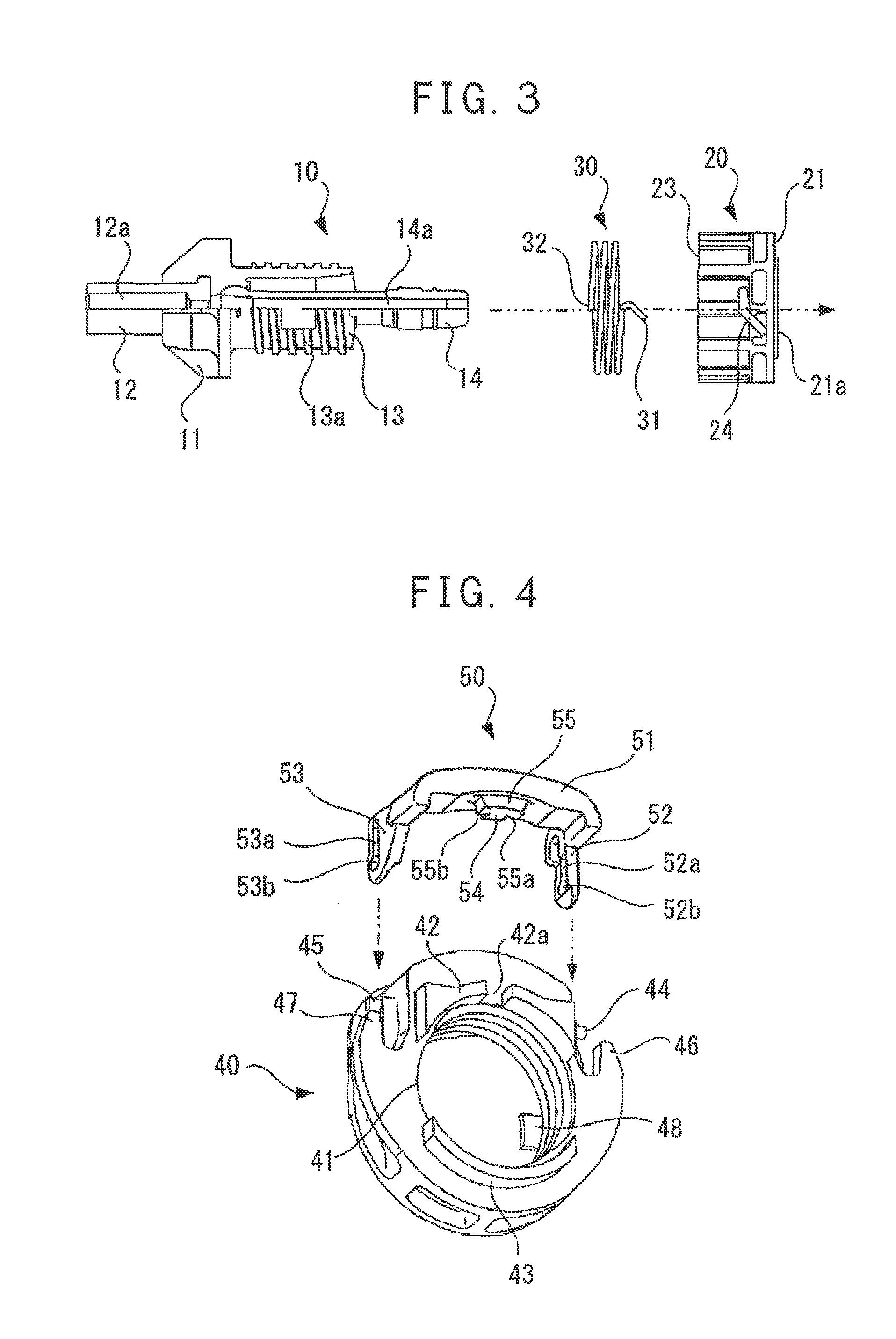
[0024]As shown in FIGS. 1 and 2, the terminal supporting device 1 comprises the main body 10, the socket 20, the biasing member 30, the stopper 40 and the lock member 50.

[0025]The main body 10 comprises a circularly cylindrical casing cap 12 and a tubular portion 13 which extend to the both sides from the center of the tubular base 11 with equally aligned along its axis line. In the tubular portion 13, a male screw 13a is formed over approximately the whole of the peripheral surface, and a guide pipe 14 is movably inserted inside the tubular portion. The casing cap 12 and the guide pipe 14 have hollow portion...


PUM


Abstract

The present invention has an object of providing a terminal supporting device which can perform a fixing operation of a cable terminal quickly and easily with a simple configuration. The terminal supporting device of the invention comprises a main body 10, a socket 20, a biasing member 30, a stopper 40, and a lock member 50. The lock member 50 includes a lock body 51 which is arranged movably between a lock position located between the socket 20 and the stopper 40 and a lock release position separated outwardly from a position located between the socket 20 and the stopper 40. The lock body 51 has a fitting projection 54, and the stopper 40 has a fitting depression 42a which fits with the fitting projection 54 of the lock body 51 at the lock position.

Description

BACKGROUND OF THE INVENTION[0001]The present invention relates to a terminal supporting device for supporting a terminal of a cable by a bracket.[0002]For example, the configuration disclosed in JP 4212832 B2 is known as a device that supports a terminal of a cable such as a control cable for vehicle. As shown in FIG. 9, this terminal supporting device 100 comprises a socket member 102 in which a cable 101 is inserted, a cylindrical nut member 103 set to a male screw 102a of the socket member 102 so as to move back and forth relative to the socket member 102 by a screw, and a stopper 104 which is interposed between a flange portion 102b of the socket member 102 and an end portion 103a of the cylindrical nut member 103 detachably. The cylindrical nut member 103 rotates in a tightening direction under the biasing force of a coil spring 105.[0003]When used, the cylindrical nut member 103 is rotated in a loosening direction against the biasing force of the coil spring 105, and the stopp...

Claims


Application Information

Patent Timeline
Patent Type & Authority Patents(United States)
IPC IPC(8): H02G3/18
CPCH02G3/22
Inventor HORINAKA, TAKAHIRO
Owner HI-LEX CORPORATION
Why Eureka
Try Eureka