Laminated optical film having a polarizer and two optical compensation layers, and liquid crystal panel and liquid crystal display apparatus using the laminated optical film

a laminated optical film and polarizer technology, applied in the field of laminated optical film, can solve the problems of film cost, /4 plate) over a wide wavelength range, and the plate cannot exhibit desired optical characteristics, so as to achieve enhanced screen contrast and reduce color shi

Active Publication Date: 2013-11-19
NITTO DENKO CORP
View PDF78 Cites 3 Cited by
  • Summary
  • Abstract
  • Description
  • Claims
  • Application Information

AI Technical Summary

Benefits of technology

[0008]The present invention has been made in view of solving the above conventional problems, and an object of the present invention is to provide a laminated optical film, a liquid crystal panel, and a liquid crystal display apparatus that are excellent in a screen contrast and have a small color shift.
[0018]According to the present invention, a screen contrast can be enhanced and a color shift can be reduced by placing a first optical compensation layer and a second optical compensation layer both having the above optical characteristics at a predetermined angle.

Problems solved by technology

Thus, the λ / 4 plate has a problem in that the plate cannot exhibit desired optical characteristics (such as functions as the λ / 4 plate) over a wide wavelength range.
However, those films have a problem with cost.
However, according to those technologies, the enhancement of a screen contrast and the reduction in a color shift are insufficient.

Method used


Image

  • Laminated optical film having a polarizer and two optical compensation layers, and liquid crystal panel and liquid crystal display apparatus using the laminated optical film
  • Laminated optical film having a polarizer and two optical compensation layers, and liquid crystal panel and liquid crystal display apparatus using the laminated optical film
  • Laminated optical film having a polarizer and two optical compensation layers, and liquid crystal panel and liquid crystal display apparatus using the laminated optical film

Examples


example 1

Polarizing Plate

[0171]A polyvinyl alcohol film was dyed in an aqueous solution containing iodine, and thereafter, the resultant film was uniaxially stretched by 6 times between rolls having different speed ratios in an aqueous solution containing boric acid to obtain a polarizer. Triacetylcellulose films (thickness: 40 μm, KC4UYW (trade name) manufactured by Konica Minola Holdings Inc.) were attached as protective layers on both sides of the polarizer via a polyvinyl alcohol-based adhesive (thickness: 0.1 μm). The in-plane retardation Re(550) of the protective layer was 0.9 nm and the thickness direction retardation Rth(550) was 1.2 nm. Thus, a polarizing plate was produced. Re(550) shows a value measured with light having a wavelength of 550 nm at 23° C.

First Optical Compensation Layer

[0172]A long norbornene-based resin film (Zeonor (trade name) manufactured by Zeon Corporation, thickness: 60 μm, photoelastic coefficient: 3.1×10⁻¹² m2 / N) was subjected to fixed-end transverse uniaxi...

example 2

Laminated Optical Film C

[0187]A laminated optical film C was obtained in the same way as in the laminated optical film A except that the lamination was performed so that the slow axis of the second optical compensation layer was parallel to the absorption axis of the polarizer of the polarizing plate.

Liquid Crystal Panel

[0188]A liquid crystal panel was obtained in the same way as in Example 1, except for using the laminated optical film C instead of the laminated optical film A. Specifically, the lamination was performed so that, in a clockwise direction with the absorption axis of the polarizer on the viewer side being a reference (0°), the slow axis of the fifth optical compensation layer was 45°, the slow axis of the third optical compensation layer was 135°, the slow axis of the second optical compensation layer was 90°, the slow axis of the first optical compensation layer was 0°, and the absorption axis of the polarizer on the backlight side was 90°, whereby a liquid crystal p...

example 3

Laminated Optical Film D

[0190]A laminated optical film D is obtained in the same way as in the laminated optical film A except for using the following film as the second optical compensation layer.

Second Optical Compensation Layer

[0191]A second optical compensation layer was obtained in the same way as in Example 1, except for stretching the film longitudinally by a stretching ratio of 1.59 times and stretching the film transversally by a stretching ratio of 1.59 times. Note that the refractive index ellipsoid of the film had a relationship of nz>nx>ny, and the in-plane retardation Re2 thereof was 10 nm, the thickness direction retardation Rth2 thereof was −80 nm, and the Nz coefficient (Rth2 / Re2) thereof was −8.0.

Liquid Crystal Panel

[0192]A liquid crystal panel is obtained in the same way as in Example 1, except for using the laminated optical film D instead of the laminated optical film A.

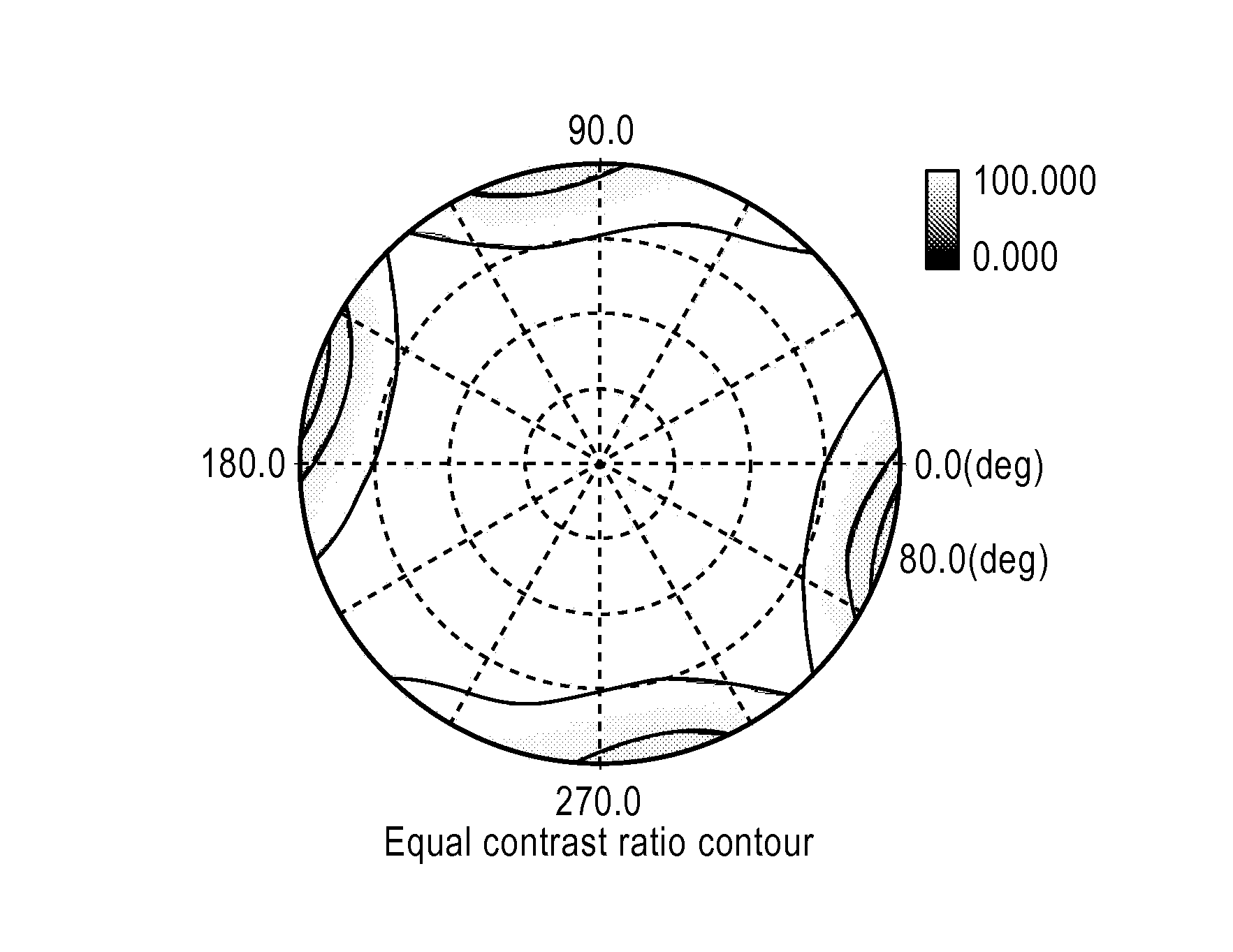
[0193]Regarding the viewing angle dependency of a contrast of the liquid crystal display appa...


PUM


Abstract

A laminated optical film according to an embodiment of the present invention includes a polarizer; a first optical compensation layer which has a refractive index ellipsoid showing a relationship of nx>ny>nz; and a second optical compensation layer which has a refractive index ellipsoid showing a relationship of nz>nx>ny, wherein the polarizer and the first optical compensation layer are placed so that an absorption axis of the polarizer is parallel to or perpendicular to a slow axis of the first optical compensation layer, and the polarizer and the second optical compensation layer are placed so that an absorption axis of the polarizer is parallel to or perpendicular to a slow axis of the second optical compensation layer.

Description

[0001]This application claims priority under 35 U.S.C. Section 119 to Japanese Patent Application No. 2008-101440 filed on Apr. 9, 2008, which is herein incorporated by reference.BACKGROUND OF THE INVENTION[0002]1. Field of the Invention[0003]The present invention relates to a laminated optical film, and a liquid crystal panel and a liquid crystal display apparatus using the laminated optical film. More specifically, the present invention relates to a laminated optical film having a polarizer and two optical compensation layers, and a liquid crystal panel and a liquid crystal display apparatus using the laminated optical film.[0004]2. Description of Related Art[0005]Various optical films each having a polarizing film and an optical compensation layer in combination are generally used in an image display apparatus (such as a liquid crystal display apparatus) so that optical compensation is performed.[0006]In general, a circularly polarizing plate which is one type of the above-mentio...

Claims


Application Information

Patent Timeline
Patent Type & Authority Patents(United States)
IPC IPC(8): G02B5/30
CPCG02B5/3033G02B5/3083G02F1/133528G02F1/133634
Inventor SABAE, MISAKITOMONAGA, MASATOSHIKOISHI, NAOKIBITOU, MASATO
Owner NITTO DENKO CORP
Why Eureka
Try Eureka