
Trailing arm mounting structure

a technology of mounting structure and trailing arm, which is applied in the direction of interconnection system, resilient suspension, vehicle components, etc., can solve the problem of not being able to suppress the pivot displacement, and achieve the effect of reducing the vertical distance, improving running stability, and suppressing the pivot displacement of the trailing arm

Inactive Publication Date: 2013-11-26
SUZUKI MOTOR CORP
View PDF11 Cites 7 Cited by
  • Summary
  • Abstract
  • Description
  • Claims
  • Application Information

AI Technical Summary

Benefits of technology

[0009]However, a distance between a pivot of the trailing arm and a bottom face of the side member is extended in this structure. Accordingly, it is not possible to suppress displacement of the pivot due to the load around the pivot without increasing the rigidity of the trailing arm bracket.
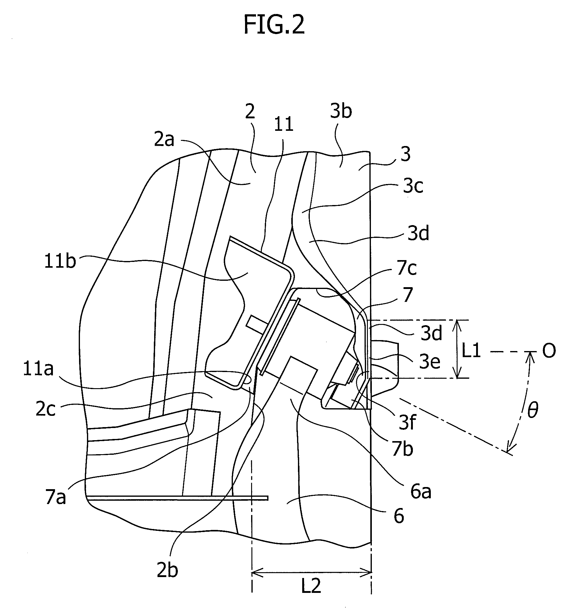
[0024]According to fourth aspect, it is possible to disperse the load applied to the mounting bracket for the trailing arm and the outside of the trailing arm shaft on the rear wheel house. Hence it is possible to improve mounting rigidity of the mounting bracket for the trailing arm and to improve supporting rigidity of the pivot, thereby reducing displacement of the pivot.

Problems solved by technology

Accordingly, it is not possible to suppress displacement of the pivot due to the load around the pivot without increasing the rigidity of the trailing arm bracket.

Method used


Image

  • Trailing arm mounting structure
  • Trailing arm mounting structure
  • Trailing arm mounting structure

Examples


Embodiment Construction

[0029]Next, an embodiment of the present invention will be described below in detail with reference to the accompanying drawings.

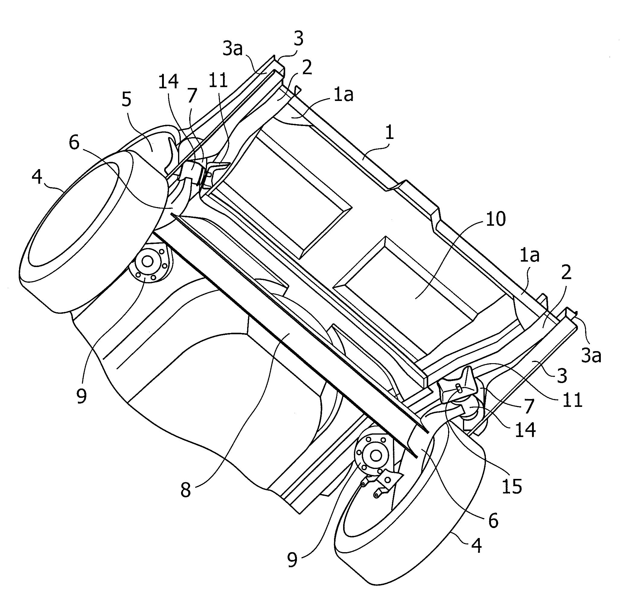
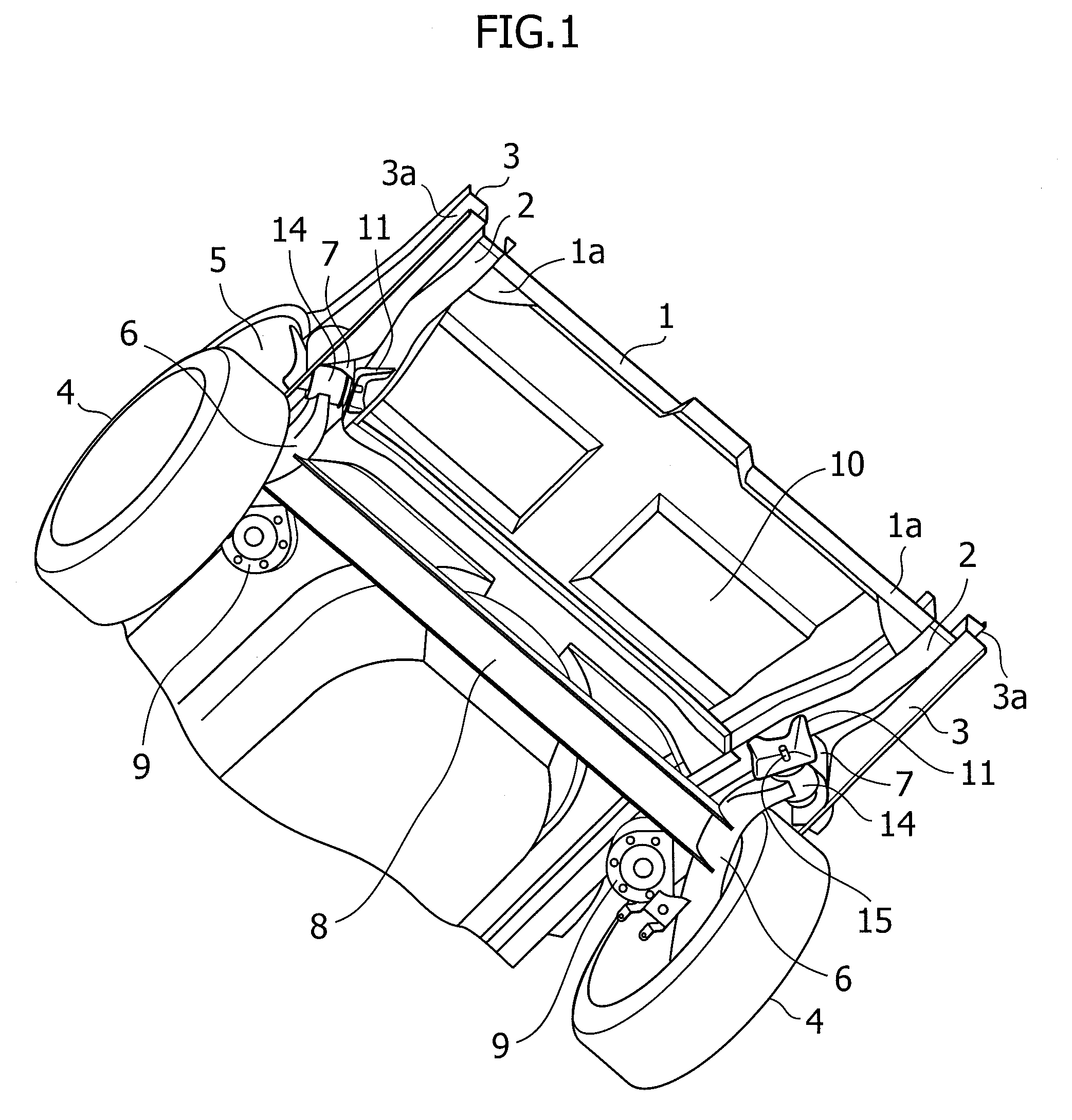
[0030]In a vehicle according to this embodiment shown in FIG. 1 to FIG. 3, a pair of right and left rear floor side members (hereinafter referred to as the side members) 2 are arranged on a rear lower face of a vehicle body 1 along a front and rear direction of the vehicle body 1. Side sills 3 are provided on right and left side lower sides 1a corresponding to door openings of the vehicle body 1 along the front and rear direction of the vehicle body 1. Side body outer panels (not shown) are arranged outside the side sills 3 so as to form side faces of the vehicle body 1.

[0031]Arch-shaped wheel houses 5 are provided on a rear side of the side sills 3 so as to cover above rear wheels 4. The rear wheels 4 are suspended by trailing arm suspensions. Here, trailing arms 6 for supporting the rear wheels 4 are supported swingably in a vertical direction by mountin...


PUM


Abstract

A trailing arm mounting structure is capable of size reduction as well as weight saving of a trailing arm bracket while ensuring mounting rigidity. In the trailing arm mounting structure, a clearance is formed between an outer sidewall of a side member and an inner sidewall of an extended portion of a side sill. In addition, an inner sidewall of a mounting bracket for a trailing arm is attached to an outer sidewall of the side member while the mounting bracket for the trailing arm is disposed in the clearance. An outer sidewall of the mounting bracket for the trailing arm is attached to the inner sidewall of the extended portion of the side sill, and a base end portion of the trailing arm is supported between the inner sidewall and the outer sidewall of the mounting bracket for the trailing arm.

Description

CROSS-REFERENCE TO RELATED APPLICATIONS[0001]The present application claims the benefit of Japanese Patent Application No. 2010-196699, filed Sep. 2, 2010, the disclosure of which is incorporated by reference herein.BACKGROUND OF THE INVENTION[0002]1. Field of the Invention[0003]The present invention relates to a trailing arm mounting structure for a trailing arm suspension configured to suspend a wheel of an automobile.[0004]2. Description of Related Art[0005]The members of a pair of a right rear floor side member and a left rear floor side member are usually arranged on a rear lower face of an automobile along a front and rear direction of a vehicle body. Meanwhile, side sills are provided along the front and rear direction of the vehicle body on side lower parts of the vehicle body corresponding to door openings.[0006]In a trailing arm suspension, a base end of a trailing arm is pivotally and swingably supported by a trailing arm bracket having a substantially U-shape, and a tip ...

Claims


Application Information

Patent Timeline
Patent Type & Authority Patents(United States)
IPC IPC(8): B60G3/12
CPCB60G3/12B60G21/0551B60G2200/20B60G2204/14B60G2204/1434
Inventor SUZUKI, TAKAYUKI
Owner SUZUKI MOTOR CORP
Learn More