Image heating apparatus and heater used in the apparatus

a technology of image heating apparatus and heater, which is applied in the direction of heater elements, instruments, electrographic processes, etc., can solve the problems of high-temperature offset, accelerated deterioration of parts in the fixing device, and prone to breakage, etc., to suppress the temperature rise of non-sheet-passing-portion, simple constitution, and low cost

Inactive Publication Date: 2013-11-26
CANON KK
View PDF23 Cites 37 Cited by
  • Summary
  • Abstract
  • Description
  • Claims
  • Application Information

AI Technical Summary

Benefits of technology

[0006]A principal object of the present invention is to provide a heater and an image heating apparatus which are capable of suppressing the non-sheet-passing-portion temperature rise at a low cost and with a simple constitution.

Problems solved by technology

When the non-sheet-passing-portion temperature is excessively increased, deterioration of parts in the fixing device is accelerated, so that there is a possibility of breakage of the parts.
Further, when the paper with a width larger than that of the small-sized paper is passed through the fixing device in a state in which the non-sheet-passing-portion temperature rise occurs, in a paper-end region (the non-sheet-passing portion during sheet passing of the small-sized paper), high-temperature offset is liable to occur.
Here, when a method such that the heat generating resistor with the NTC characteristic is formed in a linear hand-like shape on the ceramic substrate to supply electric power with respect to the longitudinal direction is employed, in many cases, it is difficult to obtain the resistance in a range in which the resistance can be used for a commercial power source.
However, in recent years, with speeding up of the operation of the image forming apparatus, theses image heating apparatuses have not adequately suppressed the non-sheet-passing-portion temperature rise, so that it is desired to provide a heater and an image heating apparatus whose resistors have a resistance value that is in the range usable for the commercial electric power and that suppresses the non-sheet-passing-portion temperature rise.

Method used


Image

  • Image heating apparatus and heater used in the apparatus
  • Image heating apparatus and heater used in the apparatus
  • Image heating apparatus and heater used in the apparatus

Examples


first embodiment

3) This Embodiment (First Embodiment)

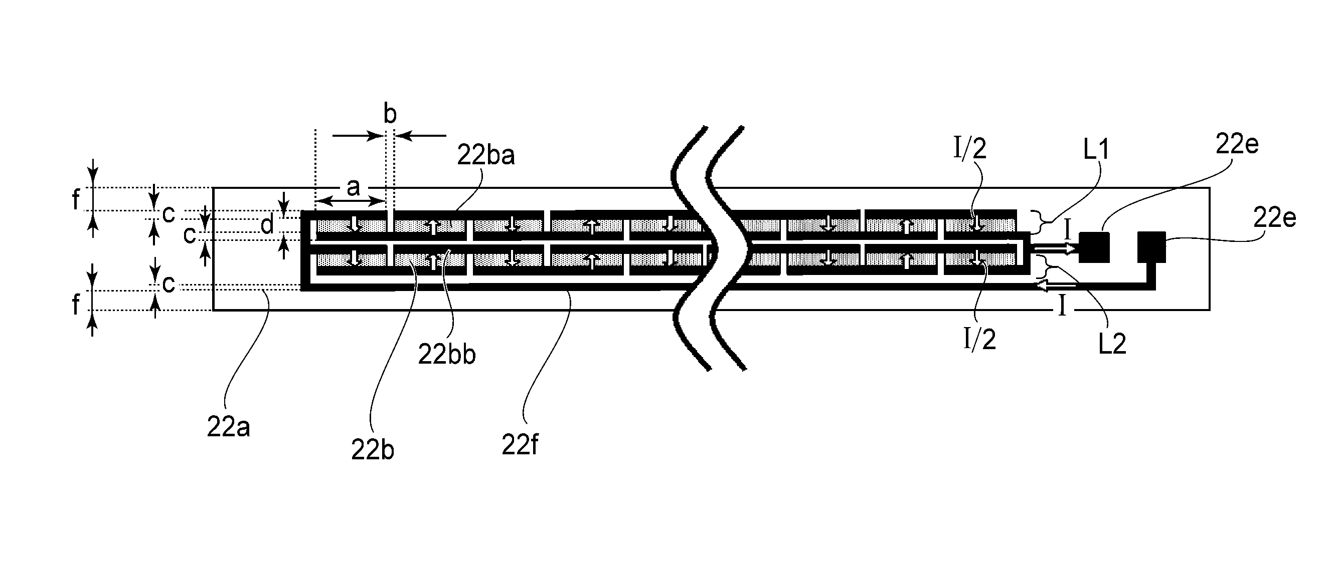
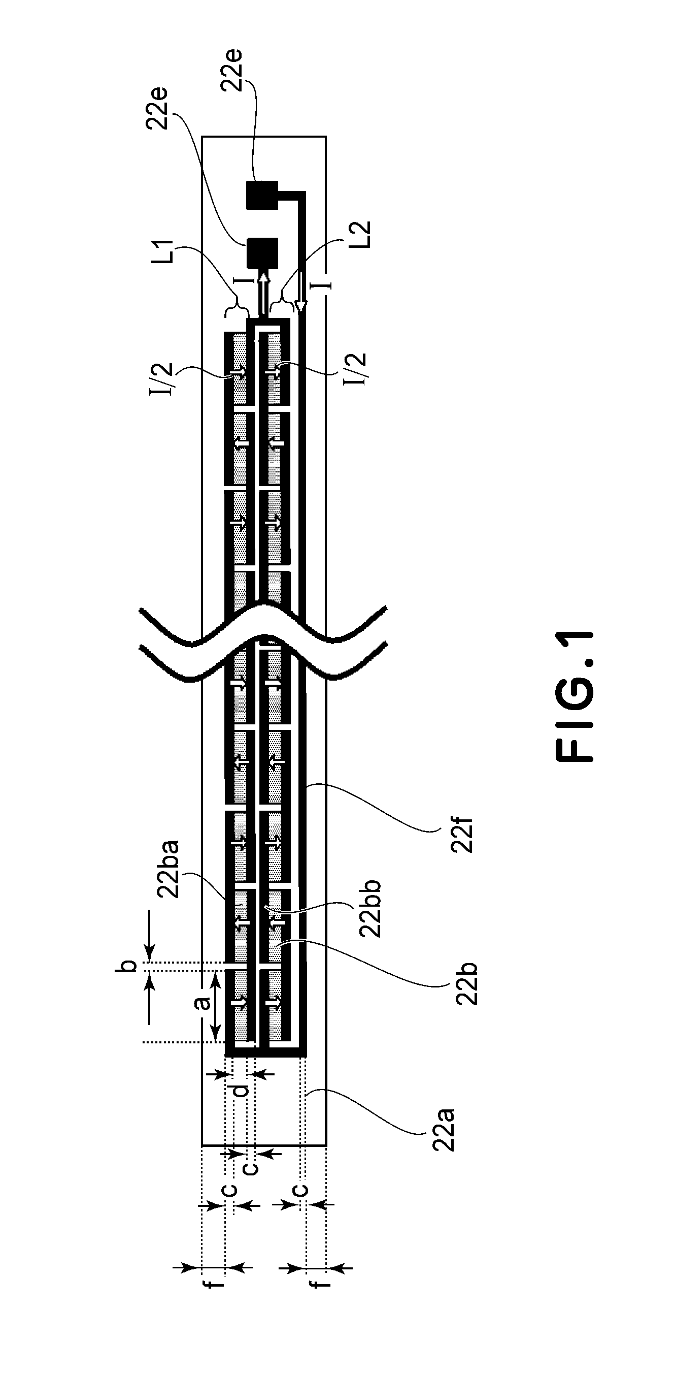
[0067]FIG. 1 shows a heater arrangement in this embodiment. In this embodiment, two parallel heat generating resistor trains (L1 and L2) each including 41 heat generating resistors 22b disposed equidistantly arranged in the longitudinal direction are formed. That is, 82 heat generating resistors 22b in total are formed on the substrate 22a. A distance b between adjacent heat generating resistors 22b constituting each heat generating resistor train was 0.5 mm. Each of the heat generating resistors 22b is 5.0 mm in longitudinal length a, 1.0 mm in widthwise length d, thus having the same shape.

[0068]Therefore, the full length of the heat generating resistor train is about 225 mm (including the distance (spacing) b) and is substantially same as those in Comparative Embodiments 1 and 2. The thickness of the heat generating resistors 22b was about 15 μm, thus being equal to that in Comparative Embodiment 1. Further, a total area of the heat generating...

second embodiment

[0102]Second Embodiment of the present invention will be described with reference to the drawings below. A difference from First Embodiment is only that different heat generating resistors of the heater and a different electroconductive pattern are used. Other constitutions of the heater, the image heating apparatus and the image forming apparatus are the same as those in First Embodiment. In First Embodiment, the two parallel heat generating resistor trains were electrically connected in parallel to make the specific resistance ((d) of FIG. 16) of the heat generating resistors larger by 4 times than the specific resistance ((b) of FIG. 16) of the heat generating resistors, thus enabling the lowering in TCR value. Therefore, in order to further increase the specific resistance to lower the TCR value, the number of the heat generating resistor trains to be electrically connected in parallel may only be required to be increased.

[0103]FIG. 10 shows a heater in the case where four paral...


PUM


Abstract

An image heating apparatus includes: an endless belt; a heater, contacted to a surface of the endless belt, provided so that a longitudinal direction thereof is parallel to a generating line direction of the endless belt; and a pressing member for forming a nip together with the endless belt. The heater includes: an elongated substrate; a first heat generating line, provided on the substrate along a longitudinal direction of the substrate, including first heat generating resistors having a negative temperature coefficient of resistance and being electrically connected in series; and a second heat generating line, provided on the substrate along the longitudinal direction of the substrate, electrically connected to the first heat generating line in parallel. The second heat generating line includes a plurality of second heat generating resistors having the negative temperature coefficient of resistance and being electrically connected in series.

Description

FIELD OF THE INVENTION AND RELATED ART[0001]The present invention relates to a heater and an apparatus using the heater and particularly relates to an image heating apparatus used in an image forming apparatus such as a copying machine, a printer or a facsimile machine. As the image heating apparatus, a fixing device (apparatus) for fixing an unfixed image on a recording material and a glossiness-improving heating device (apparatus) for improving the glossiness of an image by heating the image fixed on the recording material are cited.[0002]In an electrophotographic copying machine or printer, the fixing device for heat-fixing a toner image formed on the recording material is mounted and as one of heating types of the fixing device, there is a film-heating type of heater. In the film-heating type of heater, a ceramic heater is provided on an inner surface of a cylindrical film (fixing film) formed principally of a heat-resistant material or metal. A pressing roller is provided oppos...

Claims


Application Information

Patent Timeline
Patent Type & Authority Patents(United States)
IPC IPC(8): G03G15/20H05B3/02H05B3/16H05B3/26H05B3/10
CPCG03G15/2042G03G15/2085G03G15/2028
Inventor TSURUYA, TAKAAKISAKAKIBARA, HIROYUKI
Owner CANON KK
Why Eureka
Try Eureka