Ultrasonic transducer for use in a fluid medium

a transducer and fluid medium technology, applied in the field of ultrasonic transducers, can solve the problems of inability to use the ultrasonic transducer for measurement, poor decoupling between the ultrasonic transducer and the surrounding housing or the disadvantage of the surrounding flow tube, etc., to achieve the effect of decoupling structure-borne noise, soft material, and stable position

Inactive Publication Date: 2013-12-03
ROBERT BOSCH GMBH
View PDF28 Cites 19 Cited by
  • Summary
  • Abstract
  • Description
  • Claims
  • Application Information

AI Technical Summary

Benefits of technology

[0013]In this way, it is possible to have a separate optimization of the material properties of the housing and the matching element, the structure-borne noise decoupling being able to be ensured by the decoupling element being designed as a completely independent element. In order to ensure the decoupling, the decoupling element may have an elastomer material, for example, particularly a silicone material and / or a polyurethane. For example, one may use liquid silicone rubber, LSR. Generally speaking, the decoupling element may have at least one plastic material, especially an elastomer material, which has a Shore A hardness of less than 40, which may be less than 25. In particular, one may also use composite materials, for instance, composite materials made of at least one matrix material, especially an elastomer matrix material, and at least one filler material. Suitable filler materials may have gas occlusions, such as gas bubbles, by using elastomer foams, for example. Alternatively or in addition, solid occlusions may also be suitable for filler material, such as hollow plastic spheres, or as a component of the filler material, for example, hollow gas-filled spheres. Such a decoupling element is able to ensure superbly the abovementioned properties of the decoupling of structure-borne noise between the housing and the matching element. In order to ensure complete sealing at the same time, such a decoupling element may be combined, for instance, with the above-mentioned sealing foil. Thus, the disk-shaped matching element may be annularly fully enclosed by the decoupling element, to which the housing is adjacent on the outside. The entire end face of this system, which faces the fluid medium, may then be covered by the sealing foil, for example.
[0021]The ultrasonic transducer and the method in one or more of the specific embodiments described above, have multiple advantages compared to known ultrasonic transducers and known methods. Thus, a pressure-resistant ultrasonic transducer may be provided which, via the sealing element described, especially the sealing foil and / or the decoupling element, at overpressure of the fluid medium that is to be measured, for instance, air, takes up the corresponding force at the front side and passes it on to the housing at the circumference and on the back side in continuous material. Because of a completely encircling, as much as possible incompressible decoupling, for instance by the decoupling element described, there comes about a stable construction of the ultrasonic transducer, which the piezoelectric transducer element is able to hold in a stable position, even when there is a frontally exerted pressure coming from the side. For production reasons, one may also use only a partially encircling or extensively encircling decoupling, for example, by the decoupling element described. In general, the decoupling element may be designed always to ensure a distance between the housing and the matching element, which is used for damping.
[0022]Moreover, in the case of the configuration according to the exemplary embodiments and / or exemplary methods of the present invention, one may do without an acoustically less favorable radiation surface, that is made up of harder materials or is connected to the housing in a stable manner. Such a radiation surface, which is connected as one piece with the housing, is described, for instance, in DE 42 30 773 C1 or in EP 0 766 071 A1, which, however has the disadvantages named with respect to the material selection. These disadvantages may be circumvented by separate optimization of the individual materials. Because of one form-locking force conduction, for instance, on the back side that is optional according to the present invention, particularly via the housing, the ultrasonic transducer is still able to be designed resistant to pressure. Because of the exemplary embodiments and / or exemplary methods of the present invention, furthermore, an effective decoupling from structure-borne noise is possible, for which normally a relatively soft material is required. This decoupling, as shown above, is now able to be taken over by the decoupling element, whose material properties are able to be optimized separately. In spite of this suspension, the matching element and the piezoelectric transducer element may be designed to be relatively stable as to position, even at high counterpressures.
[0023]The proposed method makes possible the connection of the matching element to the housing via, for instance, the decoupling element and / or the sealing foil in what may be one single connecting process to form an assembly which has three or more individual parts. Subsequently, additional elements may be inserted. For instance, the piezoelectric transducer element may be inserted into the assembly only after the production of the assembly mentioned. In this way, because of forward displacement of the production of the assembly, mechanical and / or thermal stresses, which could cause harm to additional components of the ultrasonic transducer, are kept away from these additional components.

Problems solved by technology

Due to this, as a rule, approximately 99.9995% of the sound energy on the way from a piezoceramic into air is reflected back at the corresponding boundary surface, and is not usable for the measurement.
One problem with known ultrasonic transducers or ultrasonic flow meters, however, is that they have to meet the requirements of particular pressure demands.
With that, however, this sound-radiating surface is usually connected to these components, such as the transducer housing and / or the flow tube, in a hard manner, so that great coupling exists with respect to the spreading of structure-born noise.
Such a poor decoupling between the ultrasonic transducer and the surrounding housing or a surrounding flow tube is disadvantageous, however, for the signal quality of the ultrasonic transducers.
These, in turn, however, reduce the coupling efficiency of the ultrasonic signals into the fluid medium and the coupling-out efficiency of ultrasonic signals from the fluid medium into the transducer.
There exists, basically, a conflict of aims between the requirements on the pressure resistance and the required structure-born sound decoupling, since the materials required for damping the relatively hard piezoceramics for sufficient energy coupling have to have a high acoustical impedance, but with that, they don't decouple sufficiently with respect to housing materials that are also hard.
On the other hand, additionally applied materials, which would be suitable for decoupling, are too soft to hold the transducer core in a stable position, in response to a pressure exerted frontally from the side.

Method used


Image

  • Ultrasonic transducer for use in a fluid medium
  • Ultrasonic transducer for use in a fluid medium

Examples


Embodiment Construction

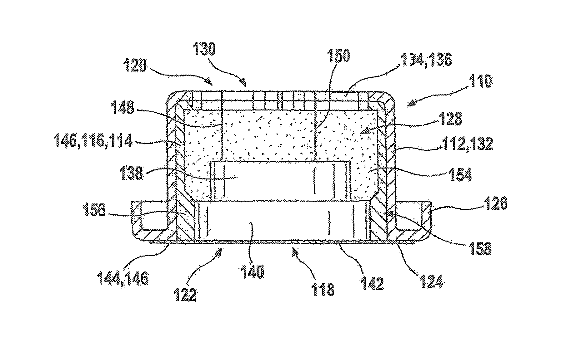
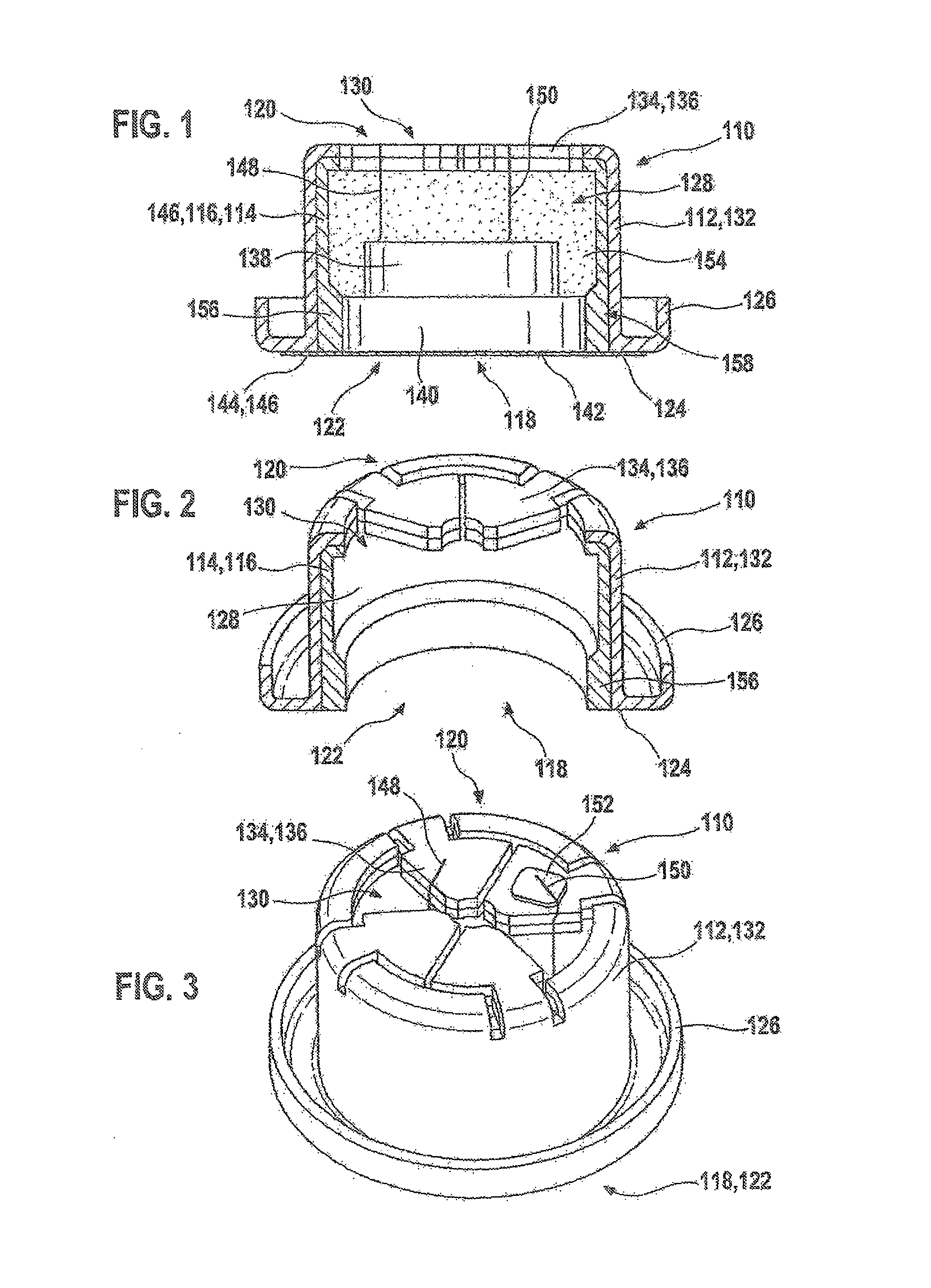
[0028]In FIGS. 1 to 3, an exemplary embodiment is shown of an ultrasonic transducer 110 in various representations. FIG. 1 shows a sectional representation as seen from the side, and FIG. 3 shows a perspective view of ultrasonic transducer 110 in a view at an angle from above. FIG. 2 shows a housing 112 of the ultrasonic transducer having a decoupling element 114 in the form of a lining 116. Additional elements of ultrasonic transducer 110 according to FIG. 1 are not shown in FIG. 2 for the sake of simplicity. The ultrasonic transducer 110 has a front side 118 which points towards the fluid medium during the operation of the ultrasonic transducer 110. Furthermore, the ultrasonic transducer 110 has a back side 120, which will, as a rule, not be in contact with the fluid medium, such as air, during operation. Housing 112 is essentially designed to be cup-shaped, and has an opening 122 on front side 118, which is particularly recognizable in FIG. 2. This opening 122 is surrounded by an...


PUM

PropertyMeasurementUnit
thicknessaaaaaaaaaa
pressuresaaaaaaaaaa
pressuresaaaaaaaaaa

Abstract

An ultrasonic transducer is described for use in a fluid medium. The ultrasonic transducer includes at least one piezoelectric transducer element and at least one matching element for promoting an oscillation injection between the piezoelectric transducer element and the fluid medium. The ultrasonic transducer also includes a housing (112), the piezoelectric transducer element being inserted in the housing. The housing has at least one opening facing the fluid medium, the matching element being inserted at least partially into the opening. The ultrasonic transducer also has at least one sealing element, which seals at least one intervening space between the matching element and the housing in such a way that an inner space of the housing is at least largely sealed from the fluid medium.

Description

FIELD OF THE INVENTION[0001]The present invention is based on known ultrasonic transducers which are used, for example, in ultrasonic flow meters in process engineering and / or in the automotive sector.BACKGROUND INFORMATION[0002]Such ultrasonic transducers or ultrasonic flow meters are used in the intake tract and / or the exhaust tract of internal combustion engines, especially for the volume flow or mass flow measurement of air. In those cases, ultrasonic transducers are typically used which are both able to emit ultrasonic waves into a fluid medium, that is, a gas and / or a fluid, and are able to receive ultrasonic waves. Ultrasonic signals are usually transmitted through the flowing fluid medium from an emitter to a receiver, and in the process, the transit time, transit time differences or phases or phase differences of the ultrasonic signals, or even the combinations of these measured variables, are measured. These signals are influenced by the flow of the fluid medium. It is pos...

Claims


Application Information

Patent Timeline
Patent Type & Authority Patents(United States)
IPC IPC(8): G01F1/20
CPCB06B1/0655G01F1/662G10K9/22G10K11/004G01P5/24Y10T29/42
Inventor MUELLER, ROLANDHUEFTLE, GERHARDHORSTBRINK, MICHAELLANG, TOBIASRADWAN, SAMIKUENZL, BERNDWANJA, ROLAND
Owner ROBERT BOSCH GMBH
Why Eureka
Try Eureka