Structure of transformer

a transformer and structure technology, applied in the direction of transformers/inductance coils/windings/connections, basic electric elements, electrical equipment, etc., can solve the problems of uneconomic transformer types, complicated overall process, and increased production costs, so as to improve the structure of transformers, simplify assembly processes, and reduce production costs

Active Publication Date: 2016-09-06
YUJING TECH CO LTD
View PDF12 Cites 2 Cited by
  • Summary
  • Abstract
  • Description
  • Claims
  • Application Information

AI Technical Summary

Benefits of technology

[0011]One main objective of the present invention is to provide an improved structure of a transformer, in which the line ends of coils are threaded through notches on a bobbin, and each of the line ends is held in place by a positioning pin with a bevel face embedded in the notch, such that each line end also functions as a terminal. Meanwhile, the bevel face on the positioning pin is capable of fastening line ends of different diameters, thus simplifying the assembly process and reducing the production cost.
[0012]Another objective of the present invention is to provide an improved structure of a transformer, in which the line ends of coils are directly connected with the circuit board or other relevant components without the need of connecting through traditional terminals and second soldering structures. As a result, the contact impedance between the output leads of the coils and the circuit board or other relevant components is lower, improving the electrical characteristics and competitiveness of the product.
[0013]Another objective of the present invention is to provide an improved structure of a transformer, in which the outer peripheral side of coils is covered by a casing to ensure the distance between the coils and magnetic cores is in compliance with the safety regulations. Additionally, an appropriate hollow opening is provided on the casing to increase the overall heat dissipating efficiency.

Problems solved by technology

However, the above transformer has the following shortcomings:1. Since the line ends of each winding of the coils are connected to the terminals by soldering, the overall process is more complicated and more costly to produce.
For smaller transformer products with lower prices, this type of transformer is not economical.2. Since the line ends of each winding of the coils are first wound and then soldered onto the terminals.

Method used


Image

  • Structure of transformer
  • Structure of transformer
  • Structure of transformer

Examples


first embodiment

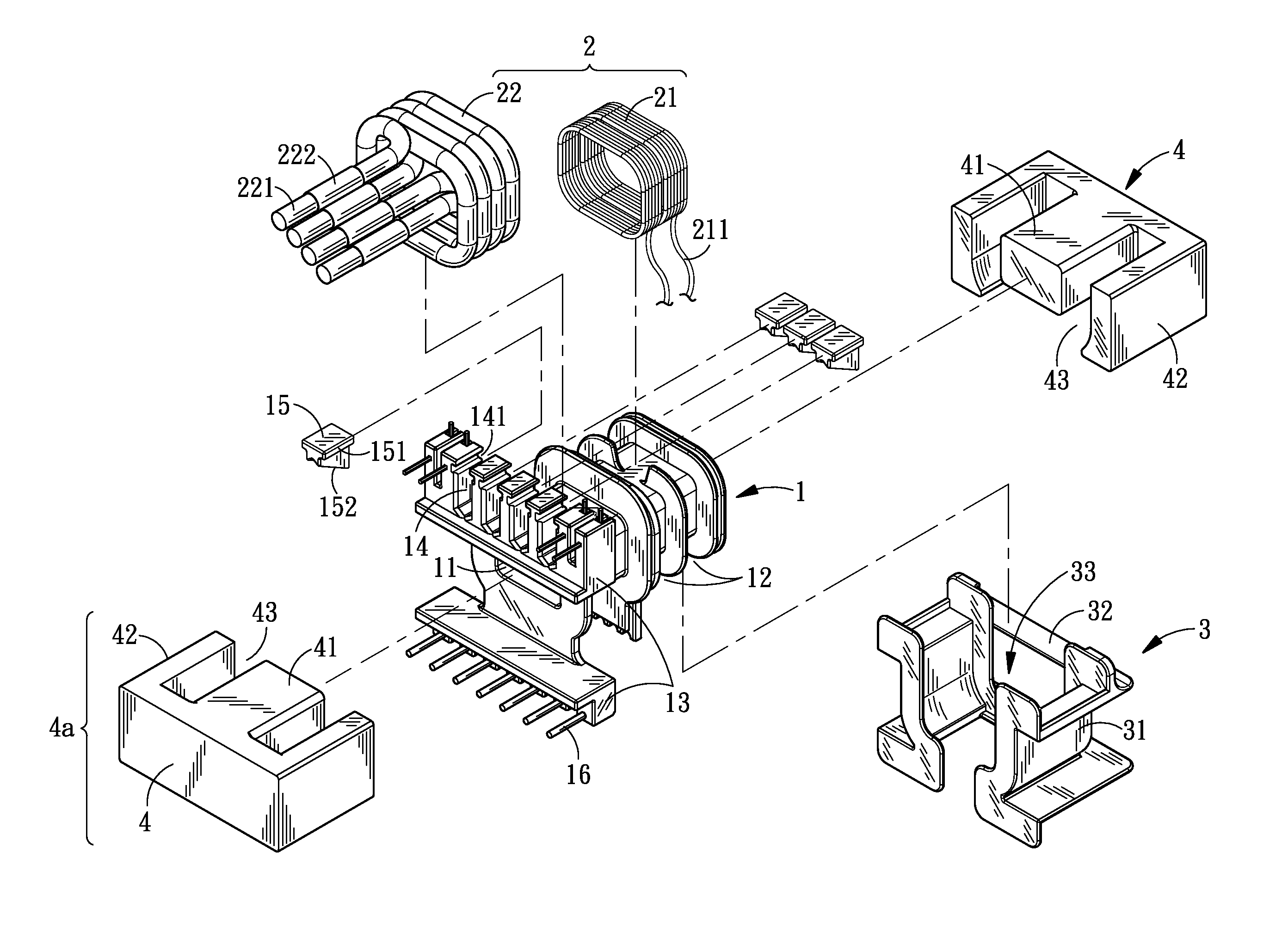
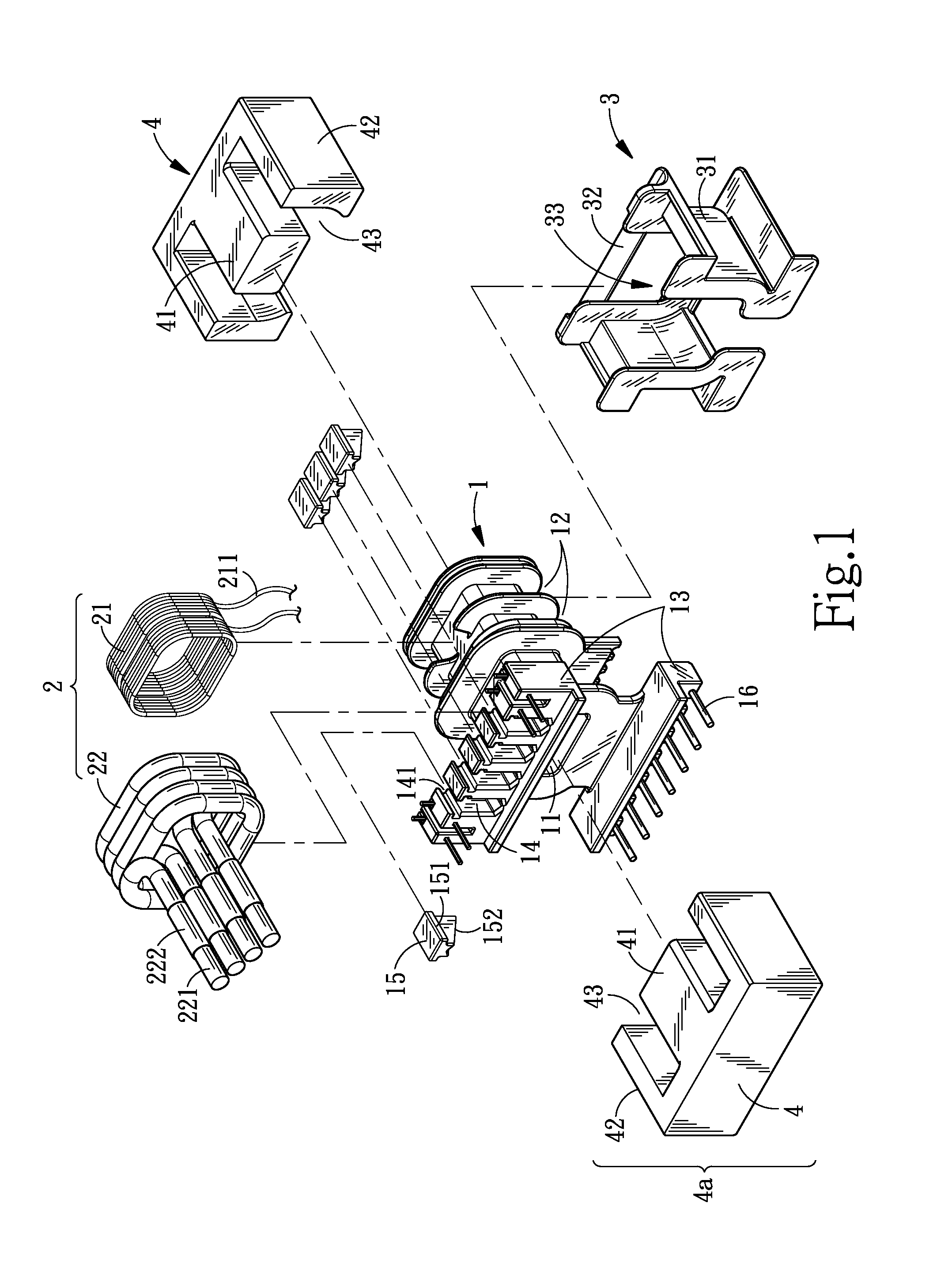
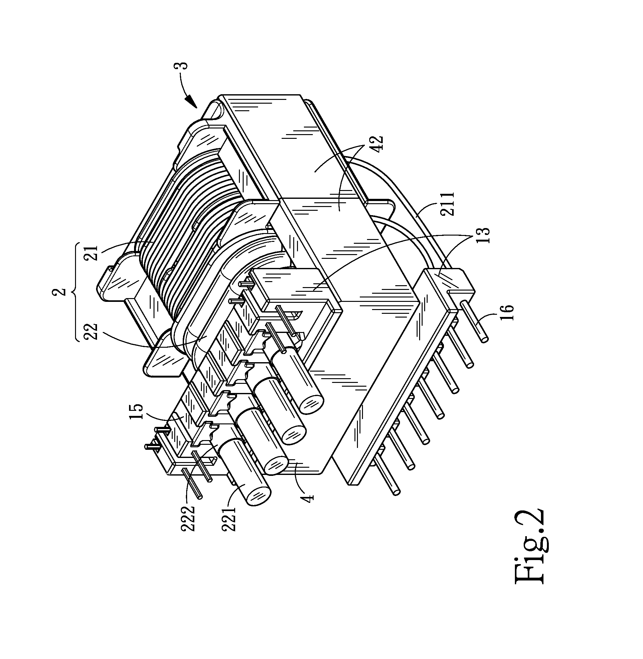
[0030]Referring to FIGS. 1 to 3, the structure of a first embodiment in accordance with the present invention mainly includes: a bobbin 1, coils 2, a casing 3 and a magnetic core set 4, wherein the bobbin 1 is provided with a center hole 11 that passes through it. At least one winding groove 12 and connecting portion 13s extending from two sides of the outer peripheral side of the center hole 11 are provided. A plurality of notches 14 with lateral openings and a plurality of pins 16 are provided on each of the connecting portions 13. Combining portions 141 (which can be guiding grooves) are provided on two sides of each notch 14 near the lateral opening. Additionally, combined portions 151 (which can be side flanges) that can be mated with the combining portions 141 are provided on two sides of a plurality of positioning pins 15, such that the positioning pins 15 provide positioning near the lateral openings within the notches 14.

[0031]The coils are wound onto the winding grooves 12...

second embodiment

[0037]In the structure of the first or the second embodiment, the positioning pins 15 or the positioning pins 17 can be independent components as described. However, in actual practice, two positioning pins 15 (or the positioning pins 17) can be combined, or even all of the positioning pins 15 (or the positioning pins 17) can be combined into a single structure, which is a variation in application and simplifies the assembly process.


PUM

PropertyMeasurementUnit
structureaaaaaaaaaa
distanceaaaaaaaaaa
sizeaaaaaaaaaa

Abstract

An improved structure of a transformer includes a bobbin covering at least a portion of a magnetic core set which has a magnetic loop passing through the bobbin, wherein winding grooves and at least one connecting portion extending sideways are provided on the outer peripheral side of the bobbin, and a plurality of notches with lateral openings are provided on the connecting portion. Coils are wound in the winding grooves of the bobbin. The coils have at least a plurality of line ends, each line end passing through a different notch. One positioning pin is embedded in each of the winding grooves near the lateral opening. The positioning pins hold the respective line ends in place by pressing against them. A casing is fitted on the outer peripheral side of the coils to create separation between the coils and the magnetic core set. The casing is provided with a hollow opening such that the outer peripheral side of the coils facing the airflow is exposed to improve the overall heat dissipating efficiency.

Description

BACKGROUND OF THE INVENTION[0001]1. Field of the Invention[0002]The invention relates to an improved structure of a transformer, and more particularly, to a transformer structure that simplifies assembly, reduces contact impedance, and ensures the distance between the outer peripheral side of the coils and the magnetic cores is in compliance with the safety regulations.[0003]2. Description of the Prior Art[0004]One basic structure of a traditional transformer is formed by winding coils (primary and secondary windings) onto the periphery of a bobbin, and providing an insulating layer on the outer periphery side of the coils (which can be several turns of insulating tapes or papers wound onto the coils), then combining the bobbin including the coils with magnetic cores. In addition, a plurality of terminals are inserted onto the bobbin, and the line ends of the windings of the coils are then soldered onto the terminals, thus completing the assembly of the transformer.[0005]However, th...

Claims


Application Information

Patent Timeline
Patent Type & Authority Patents(United States)
IPC IPC(8): H01F27/02H01F27/29H01F27/30H01F27/32
CPCH01F27/325H01F27/025H01F27/306H01F2027/297
Inventor YANG, SEN-TAI
Owner YUJING TECH CO LTD
Why Eureka
Try Eureka