Illuminated keyswitch structure and illuminating module thereof

a technology of illumination module and key switch, which is applied in the direction of legends, electrical apparatus, contact mechanisms, etc., can solve the problems of increasing the chance, increasing the difficulty of key switch structure near the light source, and unable to move up and down smoothly, so as to achieve the effect of controlling the structural siz

Active Publication Date: 2022-11-03
DARFON ELECTRONICS CORP
View PDF6 Cites 2 Cited by
  • Summary
  • Abstract
  • Description
  • Claims
  • Application Information

AI Technical Summary

Benefits of technology

[0004]An objective of the invention is to provide an illuminated keyswitch structure and an illuminating module, which uses a flat spacer to separate a base plate and a light-emitting part thereof. This structural configuration helps to control the size of the structure, ensure the distance for mixing light, and protect the light-emitting part, which prevents the light-emitting part from structurally interfering with other components above the bottom plate and causing damage.
[0005]An illuminated keyswitch structure according to an embodiment of the invention comprises: abase plate, including at least one opening; a drive circuit board, disposed under the base plate; a spacer, disposed onto the drive circuit board, the spacer having an upper surface, a lower surface, a through hole and a sidewall defining the through hole; a light-emitting part, disposed on the drive circuit board and in the through hole of the spacer, the light-emitting part having a top surface lower than or equal to the upper surface of the spacer; and a light-permeable covering structure covering above the light-emitting part; wherein the spacer comprises a top adhesive and a bottom adhesive respectively disposed on the upper surface and the lower surface of the spacer. In an variant embodiment, an illuminating module for providing back light from underneath an opening of a keyswitch base plate is introduced, which comprises the aforesaid drive circuit board, the spacer, the light-emitting part, the light-permeable covering structure, the top adhesive and bottom adhesive; wherein a total thickness of the spacer, the top adhesive, and the bottom adhesive is greater than or equal to a sum of a height of the light-emitting part and a thickness of a portion of the light-permeable covering structure above the light-emitting part. In another embodiment, the upper surface or the lower surface has an annular clearance fringe without the top adhesive or the bottom adhesive respectively, and the annular clearance fringe surrounds the periphery of the through hole. In another derived embodiment, a sum of a height of the sidewall of the through hole and thicknesses of the top adhesive and the bottom adhesive is greater than or equal to a sum of a height of the light-emitting part and a thickness of a portion of the light-permeable covering structure above the light-emitting part. Thereby, through the spacer, the structure of the illuminated keyswitch structure around the light-emitting part can keep flat, which is conducive to the control on the structural size. The spacer can prevent the light-emitting part from structurally entering the opening of the base plate, which can prevent the light-emitting part from structurally interfering with other components above the bottom plate in the illuminated key structure and causing damage.

Problems solved by technology

The convex structure will make the portion of the illuminated key switch structure near the light source appear uneven, which is not conducive to the assembly of the components of the illuminated key switch structure and the overall thin design of the illuminated keyswitch structure.
This structural configuration will increase the chance of structural interference with the structural parts above the base plate (e.g. the supports supporting the keycap), causing the keycap to fail to move up and down smoothly, or indirectly damage the light source.

Method used


Image

  • Illuminated keyswitch structure and illuminating module thereof
  • Illuminated keyswitch structure and illuminating module thereof
  • Illuminated keyswitch structure and illuminating module thereof

Examples


Embodiment Construction

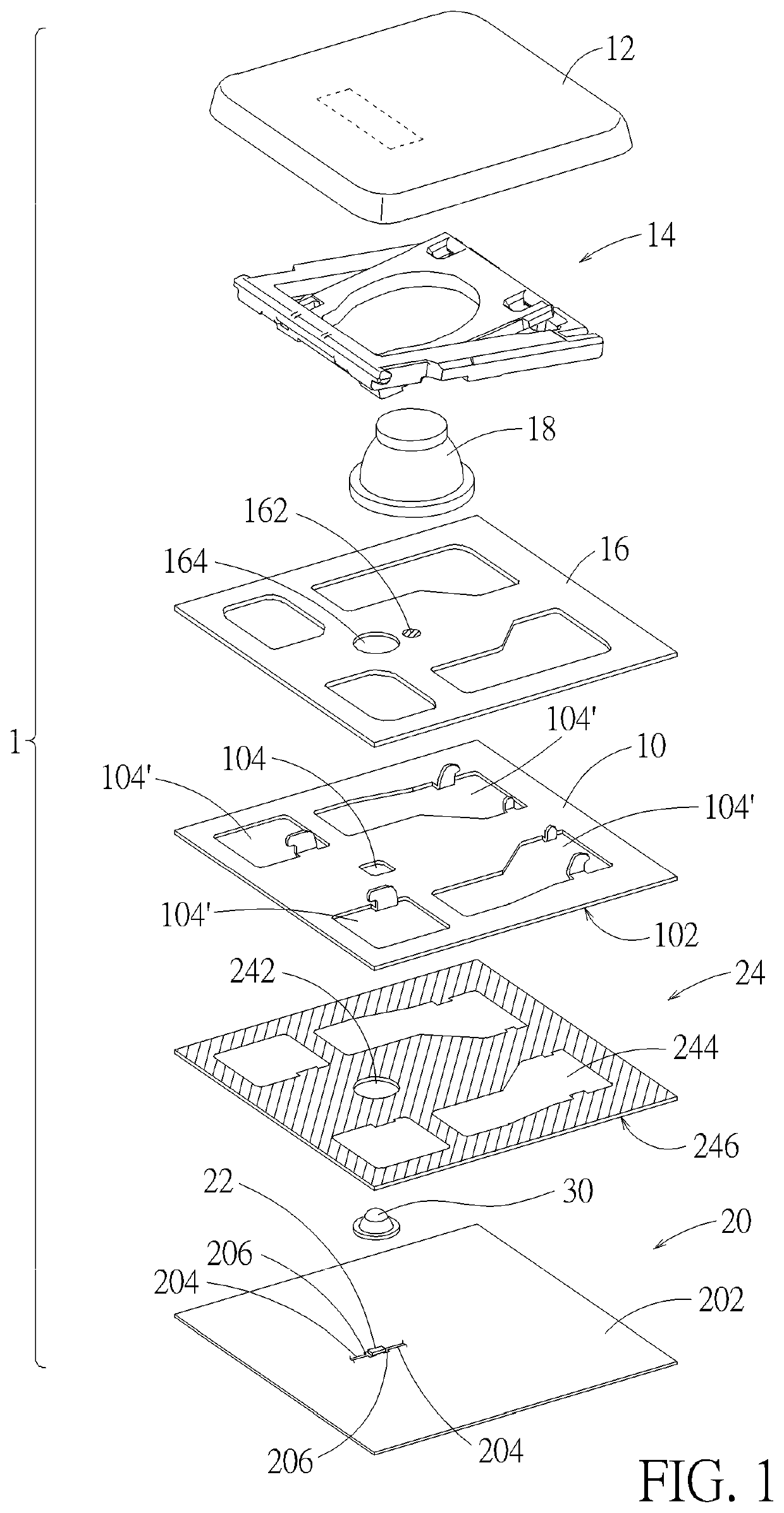
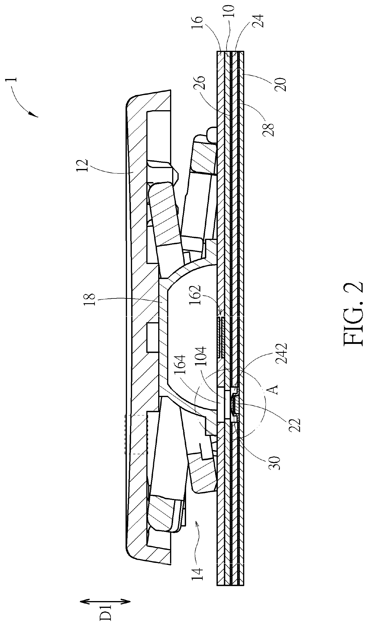
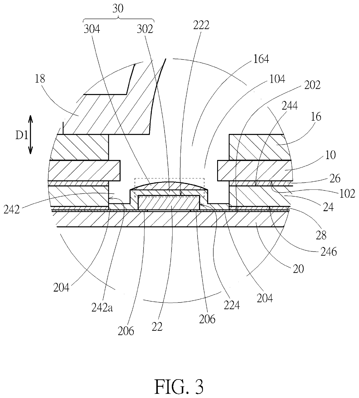
[0017]Please refer to FIG. 1 to FIG. 3. An illuminated keyswitch structure 1 according to an embodiment includes a base plate 10, a keycap 12, a lift mechanism 14, a switch circuit board 16, a resilient restoration part 18, a drive circuit board 20, a light-emitting part 22, and a spacer 24. The keycap 12 is disposed above the base plate 10. The lift mechanism 14 is connected to and between the base plate 10 and the keycap 12, so that the keycap 12 can move up and down relative to the base plate 10 through the lift mechanism 14. The switch circuit board 16 is disposed on the base plate 10 and has a switch 162 (indicated by a hatched circle in FIG. 1). The resilient restoration part 18 is disposed between the keycap 12 and the switch 162 corresponding to the switch 162. The keycap 12 can be pressed down to squeeze the resilient restoration part 18, so that the resilient restoration part 18 triggers the switch 162. The switch 162 can be triggered by a triggering protrusion located abo...


PUM


Abstract

An illuminated keyswitch structure with an illuminating module includes a base plate, a drive circuit board under the base plate, a spacer between the drive circuit board and the base plate, and a light-emitting part on the circuit board. The spacer has a through hole communicating with an opening of the base plate in a vertical direction. The light-emitting part is located in the through hole, and falls within a projection of the opening in the vertical direction. The light-emitting part has a top surface that is lower than or equal to a bottom surface of the base plate in the vertical direction. The structure of the illuminated keyswitch structure around the light-emitting part can keep flat by the spacer. The spacer can prevent the light-emitting part from structurally entering the opening, avoiding structural interference between the light-emitting part and other components above the base plate.

Description

CROSS REFERENCE TO RELATED APPLICATIONS[0001]This application is a continuation of U.S. application Ser. No. 17 / 234,808, filed on Apr. 20, 2021, which claims the benefit of Taiwan patent application No. 110100264, filed on Jan. 5, 2021, which applications are hereby incorporated herein by reference in their entirety.BACKGROUND OF THE INVENTION1. Field of the Invention[0002]The present invention relates to a keyswitch structure, and more particularly to an illuminated keyswitch structure and an illuminating module thereof.2. Description of the Prior Art[0003]Some illuminated keyswitch structures on the market are equipped with an exclusive light source under the base plate to emit light upward. The base plate forms an opening corresponding to the light source so that the light can pass through the base plate. Generally, in order to avoid electrostatic discharges between the base plate and the light source and protect the light source, an insulation sheet is attached onto the light so...

Claims


Application Information

Patent Timeline
Patent Type & Authority Applications(United States)
IPC IPC(8): H01H13/02H01H13/14H01H13/04
CPCH01H13/023H01H13/14H01H13/04H01H13/52H01H3/125H01H13/83H01H2219/056H01H2219/04H01H2219/036
Inventor HUANG, HENG-YIHO, HSIN-CHENGCHEN, YUAN-BAO
Owner DARFON ELECTRONICS CORP
Why Eureka
Try Eureka