Supercharge Your Innovation With Domain-Expert AI Agents!

Valve assembly

a valve assembly and valve body technology, applied in the field of valve assembly, can solve the problems of affecting the operation of the valve, the flow restriction, and the damage to one or more components of the valve assembly and/or the fluid pipeline system, so as to relieve the pressure difference, prevent damage to components, and relieve the effect of pressure differen

Active Publication Date: 2013-12-03
MARSHALL EXCELSIOR CO
View PDF24 Cites 2 Cited by
  • Summary
  • Abstract
  • Description
  • Claims
  • Application Information

AI Technical Summary

Benefits of technology

[0008]A valve assembly comprises a housing having a first chamber, a second chamber, and a valve seat disposed between the first and second chambers. A valve head is disposed in the housing and is moveable relative to the housing between an open position spaced from the valve seat and a closed position engaged with the valve seat. The valve head defines a bore therethrough along an axis. A valve stem is coupled to the valve head for moving the valve head between the open and closed positions. The valve stem is disposed in the bore and is moveable relative to the valve head from a sealed position preventing fluid communication through the bore to an unsealed position allowing fluid communication through the bore for relieving pressure differences between the first chamber and the second chamber when the valve head is in the closed position. An intermediate member is separate from and coupled to the valve seat and the valve head in the bore. The intermediate member is axially fixed to one of the valve stem and the valve head. The other of the valve stem and the valve head defines a travel space with the intermediate member retained in the travel space between the valve stem and the valve head. The travel space is sized larger than the intermediate member along the axis for allowing selective movement of the valve stem relative to the valve head between the sealed and unsealed positions.
[0009]The valve assembly advantageously allows for the pressure between the first and second chambers to approach equilibrium before the valve head is moved to the open position. This is beneficial when pressure in the second chamber is greater than that in the first chamber such that the pressure in the second chamber urges the valve head toward the closed position. The valve stem can be moved to the unsealed position to allow the pressures between the first and second chambers to equilibrate prior to moving the valve head to the open position. Because the pressures between the first and second chambers are equilibrated, the force required to move the valve head from the closed position to the open position is reduced.
[0011]The check valve advantageously relieves the pressure difference between the second and first chambers. This pressure relief prevents damage to components of the valve assembly and the system to which the valve assembly is connected. This check valve is also beneficial when the pressure in the second chamber urges the valve head toward the closed position. The check valve relieves the pressure difference such that the force required to move the valve head from the open position to the closed position is reduced.
[0012]The present invention also includes a valve assembly comprising a housing defining a chamber having an inlet and an outlet spaced from each other along a first axis. The inlet has an inlet diameter and the outlet has an outlet diameter greater than or equal to the inlet diameter. A valve stem is moveably engaged with the housing and extends along a second axis into the chamber. A valve head is disposed in and moveable relative to the housing between an open position and a closed position. The valve head defines a bore extending therethrough along the second axis with the valve stem coupled to the valve head in the bore for moving the valve head along the second axis between the open and closed positions. The housing includes a valve seat disposed in the chamber between the inlet and the outlet with the valve seat extending perpendicular to the second axis. The valve head engages the valve seat in the closed position and is spaced from the valve seat in the open position. The second axis extends at an acute angle relative to the first axis and the housing defines a pocket extending along the second axis for receiving the valve head in the open position to reduce flow restrictions between the inlet and the outlet.
[0013]Such a configuration reduces flow restrictions to increase the flow through the valve assembly. Specifically, outlet diameter being greater than or equal to the inlet diameter and the valve head being recessed into the pocket reduces flow restrictions between the inlet and the outlet. The valve seat being perpendicular to the second axis and the second axis extending at an acute angle relative to the first axis also reduces flow restrictions. This configuration ensures that the fluid does not pass through any space in which the cross-sectional area, normal to the flow, is less than the cross-sectional area of the inlet and outlet, which advantageously increases the flow through the valve assembly.

Problems solved by technology

Additionally, the pressure on the back portion may become great enough to cause damage to one or more elements of valve assembly and / or the fluid pipeline system.
In addition, valve assemblies of the prior art have internal components or structure that cause flow restrictions that interfere with the fluid flow.
This interference can produce energy loss as fluid flows from an inlet to outlet of the valve assembly thereby decreasing fluid flow performance.

Method used


Image

  • Valve assembly
  • Valve assembly
  • Valve assembly

Examples


first embodiment

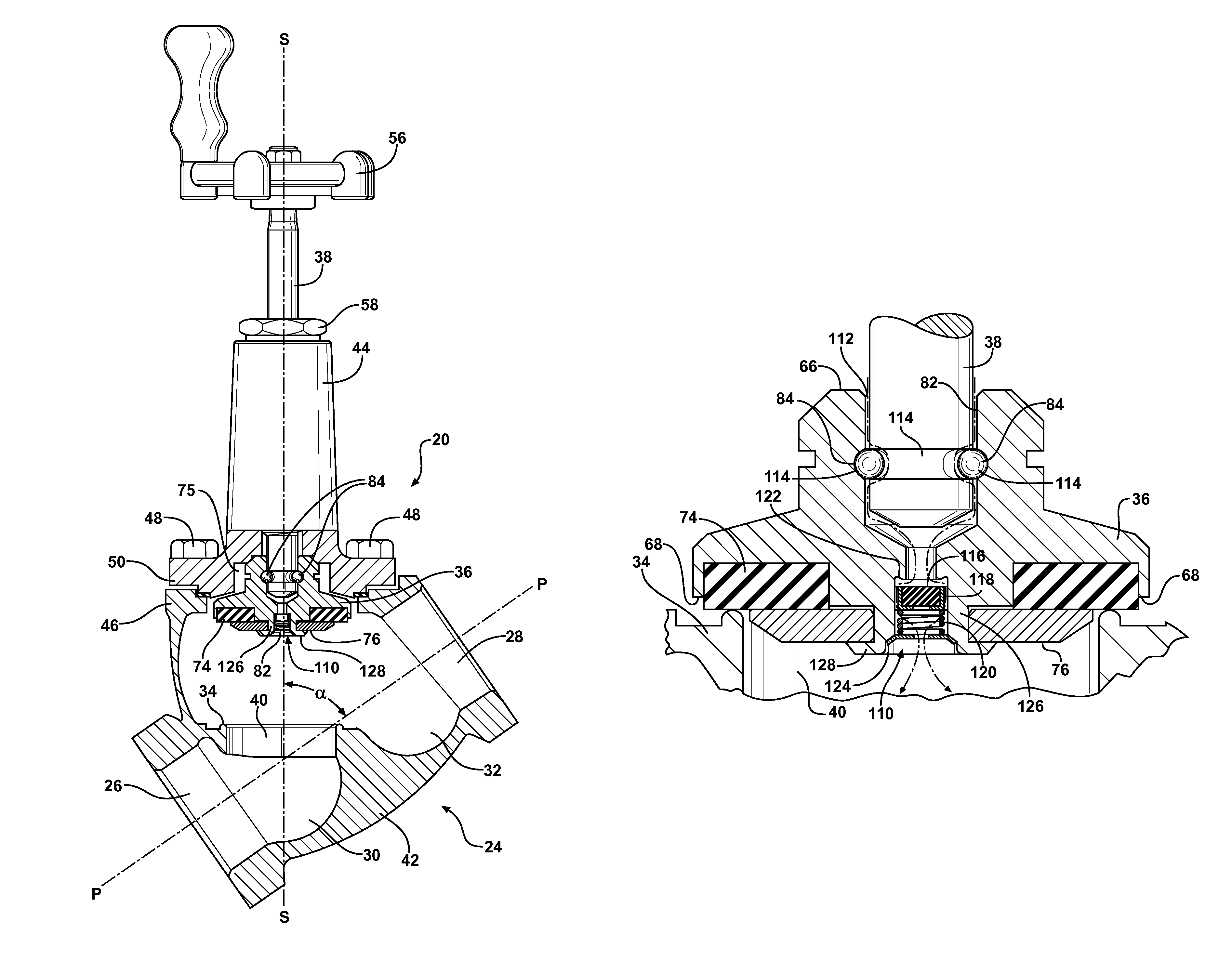
[0051]In the first embodiment, as shown in FIGS. 3-5, the valve stem 38 and the valve head 36 define corresponding races 90. The corresponding races 90 have a shape and size corresponding to the intermediate members 84. The intermediate members 84 are retained between the valve stem 38 and the valve head 36 in the corresponding races 90 for engaging the valve stem 38 to the valve head 36. Typically, the corresponding races 90 are each continuous around the circumference of the bore 82; however, it is to be appreciated that one of the corresponding races 90 can be discontinuous, i.e., a plurality of discontinuous races spaced from each other about the circumference of the bore.

[0052]The intermediate members 84 in the corresponding races 90 retain the valve head 36 in position along the stem axis S relative to the valve stem 38. The intermediate members 84 roll along the corresponding races 90 such that the valve head 36 swivels about the valve stem 38. This configuration with the val...

second embodiment

[0063]The valve assembly 20 of the second embodiment operates as follows. Rotation of the valve stem 38 relative to the housing 24 moves the valve stem 38 between the sealed and unsealed positions and moves the valve head 36 between the open and closed positions. When the valve head 36 is in the closed position, the first wall 106 engages the intermediate members 84 such that the valve stem 38 is in the sealed position with the bore seal 98 disposed between and sealing to the end 96 of the valve stem 38 and the ledge 94 of valve head 36, as shown in FIGS. 7B and 8B.

[0064]To move the valve head 36 to the open position, the hand wheel 56 is rotated counter-clockwise thereby traversing the valve stem 38 back up through the bonnet 44. Because the travel space 100 is larger than the intermediate members 84 along the stem axis S, the valve stem 38 moves from the sealed position to the unsealed position, i.e., the end 96 of the valve stem 38 separates from the bore seal 98, before the seco...


PUM


Abstract

A valve assembly includes a housing having a first chamber, a second chamber, and a valve seat disposed therebetween. A valve head disposed in the housing and is moveable between an open position and a closed position. The valve head defines a bore extending along an axis from the first chamber to the second chamber when the valve head is in the closed position. A valve stem is disposed in the bore and is coupled to the valve head in the bore for moving the valve head between the open and closed positions. The valve assembly allows for selective fluid communication between the first and second chambers to alleviate pressure differences between the first and second chambers. In one embodiment, the valve stem moves in the bore between a sealed position and an unsealed position. In another embodiment, a check valve is disposed in the bore.

Description

CROSS-REFERENCE TO RELATED APPLICATIONS[0001]This patent application claims priority to and all the benefits of U.S. Provisional Patent Application No. 61 / 101,804, which was filed on Oct. 1, 2008, and U.S. Provisional Patent Application No. 61 / 166,088, which was filed on Apr. 2, 2009, the entire contents of which are expressly incorporated herein by reference.BACKGROUND OF THE INVENTION[0002]1. Field of the Invention[0003]The present invention relates to a valve assembly, and more specifically, a valve assembly for controlling pressures on opposing sides of the valve assembly prior to opening the valve assembly.[0004]2. Description of the Related Art[0005]Valve assemblies are used for regulating flow in a fluid pipeline system. These valve assemblies comprise a housing having a first chamber, a second chamber, and a valve seat disposed between the first and second chambers. A valve head is disposed in the housing and is moveable relative to the housing between an open position space...

Claims


Application Information

Patent Timeline
Patent Type & Authority Patents(United States)
IPC IPC(8): F16K39/02F16K1/02
CPCF16K1/10F16K1/36F16K1/485F16K39/024F16K43/008F16K1/48Y10T137/7904Y10T137/86944Y10T137/86968Y10T137/87Y10T137/88022F16K15/18F16K31/504
Inventor ZUCK, JAMES C.HOFFMAN, ALEX L.
Owner MARSHALL EXCELSIOR CO
Features
  • R&D
  • Intellectual Property
  • Life Sciences
  • Materials
  • Tech Scout
  • Unparalleled Data Quality
  • Higher Quality Content
  • 60% Fewer Hallucinations
Learn More