Mounting bracket

a mounting bracket and bracket technology, applied in the direction of building scaffolds, doors/windows, light support devices, etc., can solve the problems of complex structure, difficult installation, and inability to meet the real distance of the rack-mount module, and achieve the effect of convenient installation

Active Publication Date: 2013-12-03
KING SLIDE WORKS CO LTD
View PDF12 Cites 27 Cited by
  • Summary
  • Abstract
  • Description
  • Claims
  • Application Information

AI Technical Summary

Benefits of technology

[0013]The primary object of the present invention is to provide a mounting bracket which has at least one pin that is transversely adjustable so as to be easily installed to an equipment rack.

Problems solved by technology

However, when the distance between the holes in the vertical support columns on two sides of the equipment rack includes a larger tolerance which causes the combination width of the mounting brackets, rails and rack-mount module cannot match with the real distance, because the pins on the mounting brackets are engaged with the holes in the vertical support columns of the equipment rack with only very small gap which is not allowed to be adjusted in a lateral direction.
Therefore, the installation is difficult and even cannot be finished.
Besides, when rack-mount module has small tolerance, the pins on the mounting brackets cannot be properly adjusted to complete the installation.

Method used


Image

  • Mounting bracket
  • Mounting bracket
  • Mounting bracket

Examples


Embodiment Construction

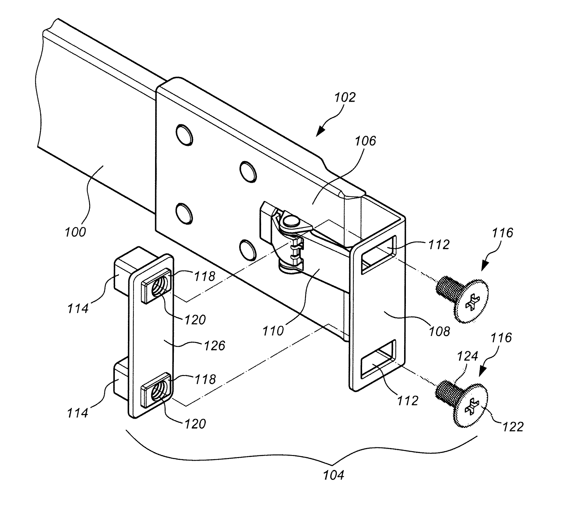
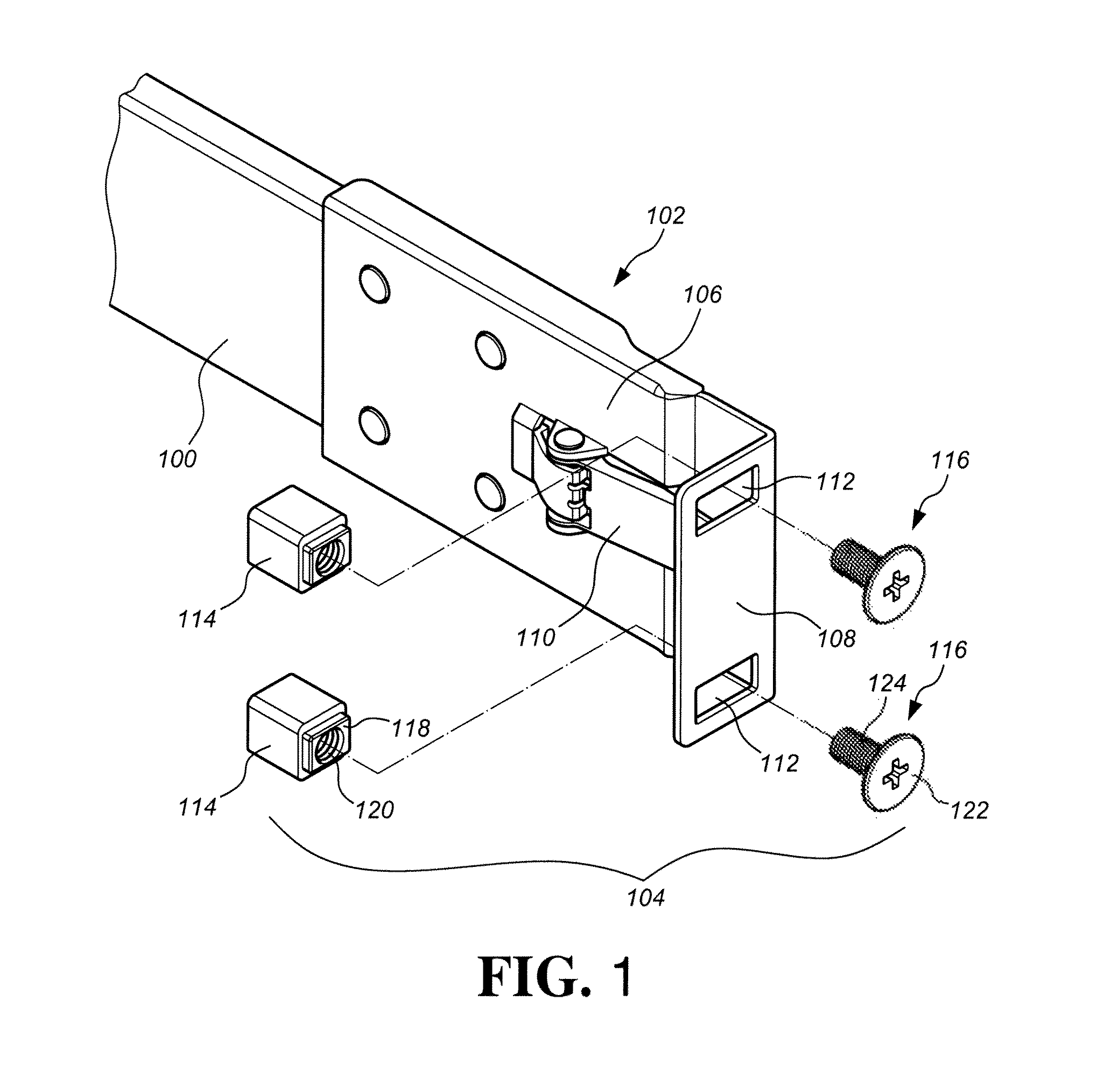
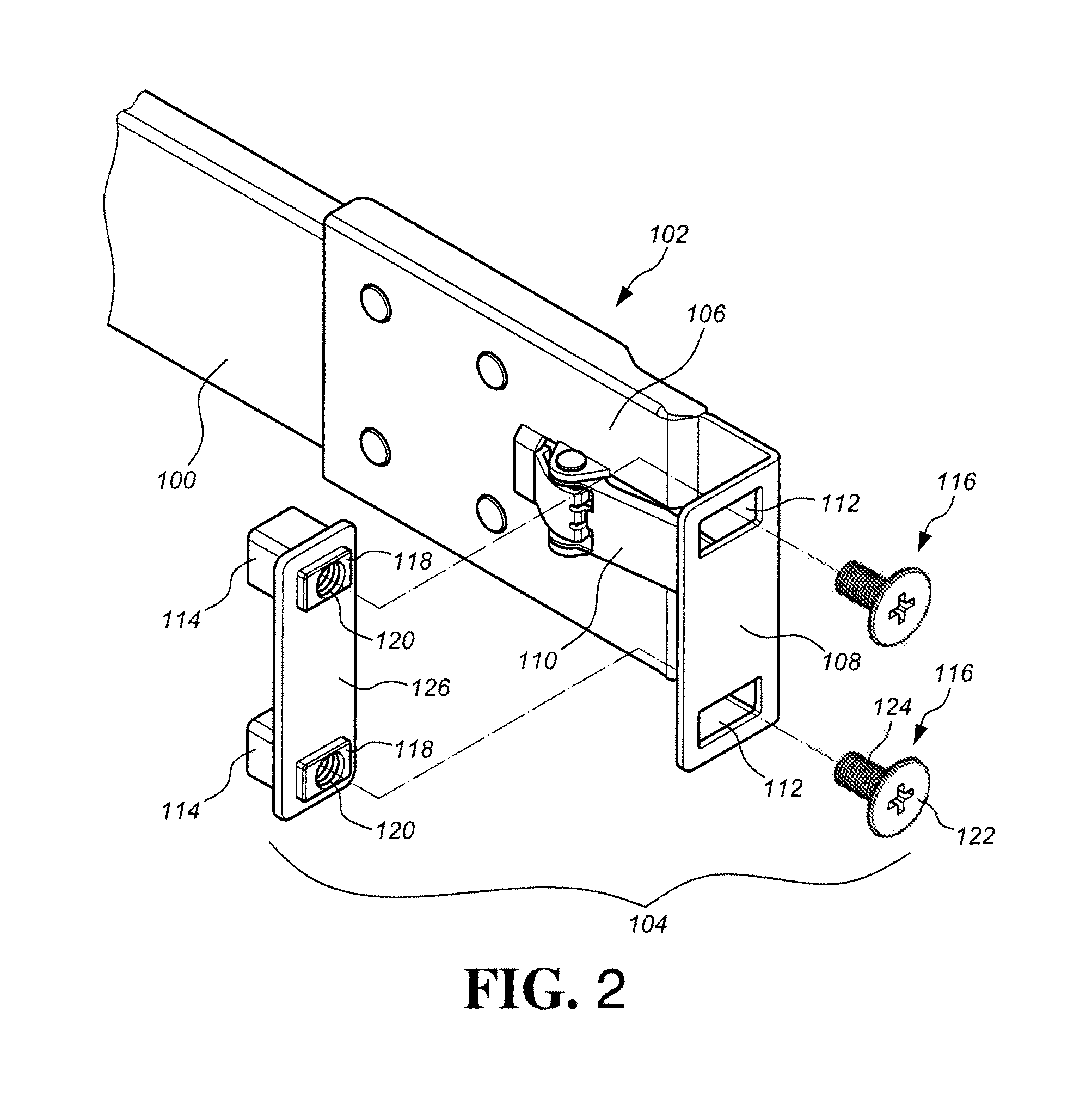
[0025]Referring to FIG. 1, the first embodiment of the present invention comprises a rail 100, a mounting bracket 102 connected to an end of the rail 100, and a pin assembly 104 connected to the mounting bracket 102. The mounting bracket 102 comprises a side plate 106 and an end plate 108 extending substantially perpendicularly from an end of the side plate 106. A stop 110 is connected to the side plate 106 of the mounting bracket 102 and extends toward the end plate 108. The side plate 106 is connected to the rail 100 and the end plate 108 has two elongate holes 112. The pin assembly 104 comprises two sets of parts so as to be located corresponding to the two elongate holes 112 of the end plate 108. Each set of parts comprises a pin 114, a fixing member 116 and a protrusion 118 located between the pin 114 and the fixing member 116. The pin 114 has a connection hole 120 such as a threaded hole. The fixing member 116 comprises a head 122 and a shank 124 extending from the head 122. T...


PUM


Abstract

A mounting bracket includes an end plate perpendicularly extending from a side plate and having an elongate hole. A pin assembly includes a pin, a protrusion and a fixing member, wherein the pin is connected to the protrusion and contacts the end plate. The protrusion is located in and movable in the elongate hole. The thickness of the protrusion is larger than that of the end plate. The fixing member includes a head and a shank extending from the head. The shank connects the pin and the protrusion. By this arrangement, the fixing member and the pin clamps the protrusion to be movably engaged with the elongate hole. The pin is adjustably moved in the elongate hole by the protrusion in the elongate hole of the end plate.

Description

FIELD OF THE INVENTION[0001]The present invention relates to a mounting bracket, and more particularly, to a mounting bracket which is connected to a rail and adjustably connected to a support column of an equipment rack by a pin assembly of the mounting bracket.BACKGROUND OF THE INVENTION[0002]U.S. Pat. No. 7,694,926 to Allen et al discloses a mounting bracket 200 which includes a base member 202 with a side plate 204 and an end plate 206 connected to the side plate 204. Two pins 210 are connected to the end plate 206. A four-rack equipment rack 100 includes four vertical support columns 104 which are arranged as a square and each vertical support column 104 includes a plurality of holes 208. When assembling, two mounting brackets are respectively connected to two ends of the rail and each mounting bracket has two pins which extend through the holes in the vertical support columns of the equipment rack, such that the rail is connected to the equipment rack. When the two rails are c...

Claims


Application Information

Patent Timeline
Patent Type & Authority Patents(United States)
IPC IPC(8): A47F7/00
CPCH05K7/1421H05K7/1489
Inventor CHEN, KEN-CHINGTSENG, I-MINGWANG, CHUN-CHIANG
Owner KING SLIDE WORKS CO LTD
Why Eureka
Try Eureka