
Motor support device for heating, ventilation and/or air-conditioning system

a technology for motor vehicles and support devices, which is applied to support/enclose/cases, liquid fuel engine components, portability frames, etc., can solve the problems of unsatisfactory standardization of decoupling, multiple vibrations, and inability to prevent any type of vibration from heating, ventilation and/or air conditioning systems. achieve the effect of improving the situation

Active Publication Date: 2013-12-03
VALEO SYST THERMIQUES
View PDF27 Cites 54 Cited by
  • Summary
  • Abstract
  • Description
  • Claims
  • Application Information

AI Technical Summary

Benefits of technology

The patent text describes a decoupling means for reducing vibrations caused by a motor and a blower wheel in a vehicle. The decoupling means includes a fourth side with at least one recess that absorbs both axial and tangential vibrations. This improves the comfort of vehicle passengers. The recess creates flexibility while maintaining rigidity. The radial planes are located so that the motor can be arranged in a horizontal or vertical position. The distribution of the decoupling means are standardized, reducing production costs. Each radial plane includes three decoupling means distributed with an angular offset of 120°, creating uniformity of forces and optimal damping of vibrations.

Problems solved by technology

These decoupling means are effective only for a certain type of vibrations and do not enable the transmission of any type of vibrations to the heating, ventilation and / or air-conditioning system to be prevented.
However, when a motor drives a blower wheel, a number of phenomena add up and cause a multitude of different vibrations.
Second, a “pumping” phenomenon due to the suction of air by the blower wheel as well as the deformation of the wheel causes an axial movement of the motor.
This is not satisfactory from the perspective of standardization of the decoupling means used or from the perspective of its location in the motor support device.
The decoupling means of the prior art are not suitable for decoupling the motor from the motor support regardless of the position of the motor, i.e. whether the motor is in the horizontal or the vertical position.
Moreover, not all of the sound disturbances created by this multitude of vibrations are dealt with.
The comfort of passengers in the vehicle is therefore not optimal.

Method used


Image

  • Motor support device for heating, ventilation and/or air-conditioning system
  • Motor support device for heating, ventilation and/or air-conditioning system
  • Motor support device for heating, ventilation and/or air-conditioning system

Examples


first embodiment

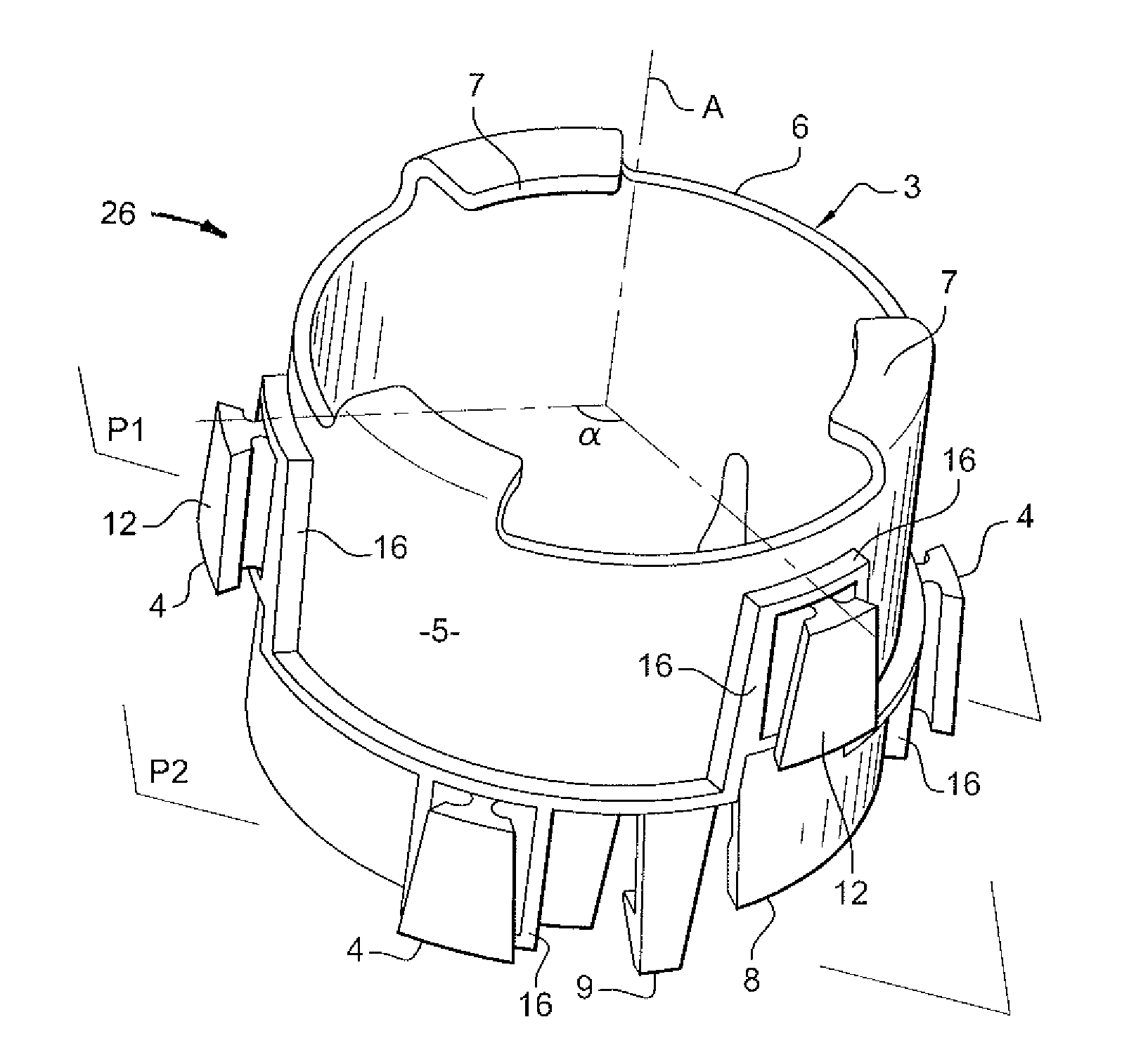
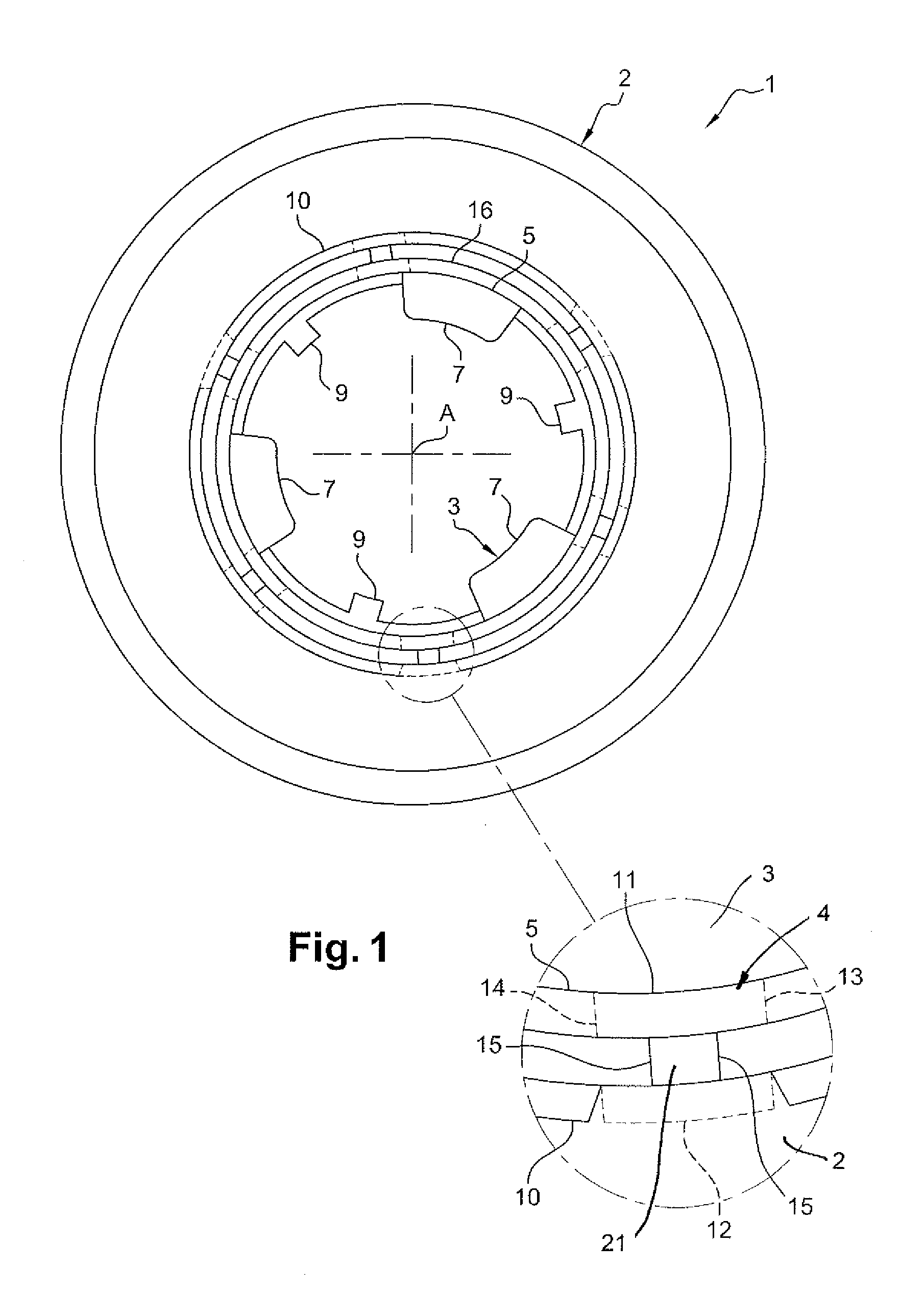
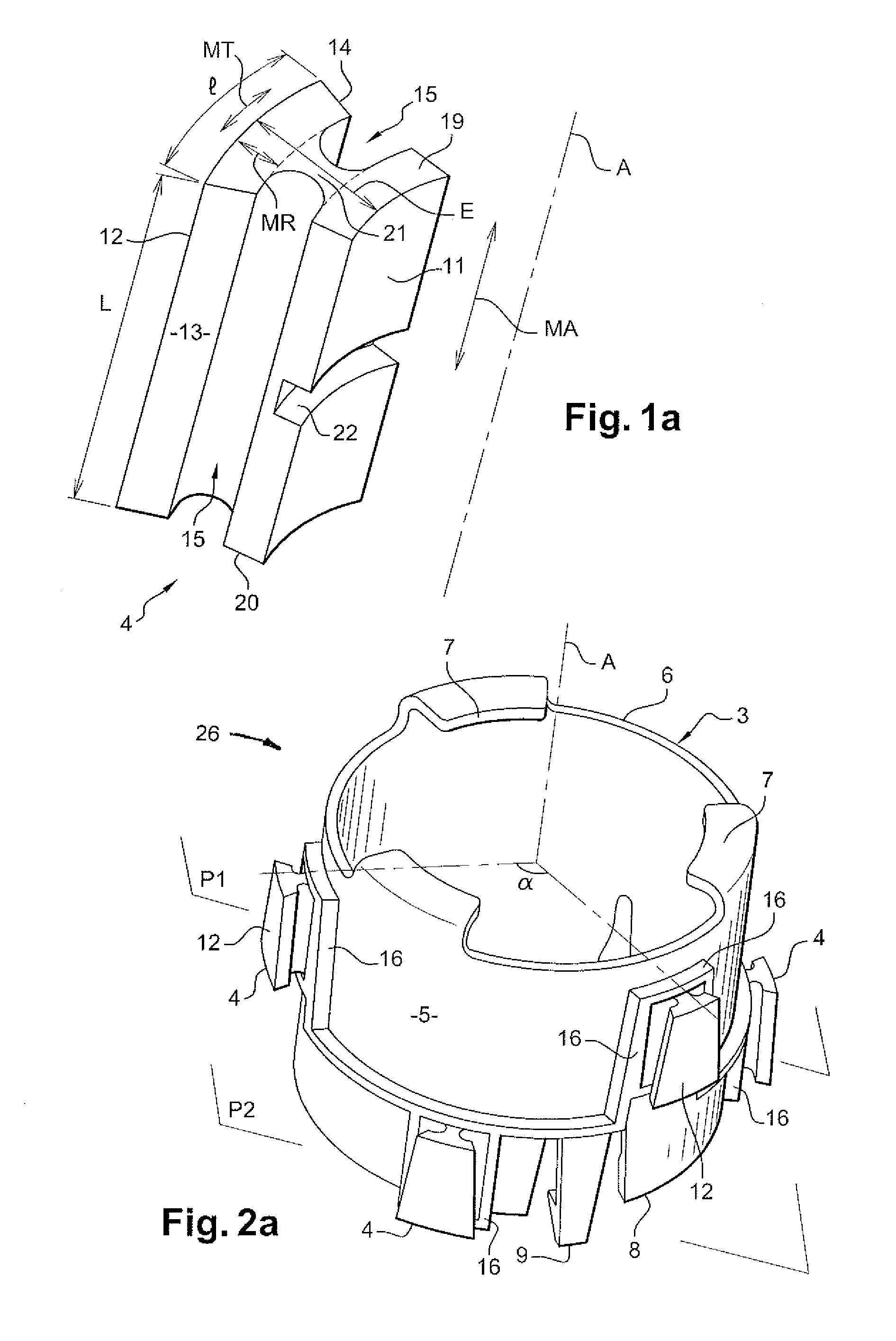
[0034]FIG. 1 shows the support device 1 according to a The support device 1 includes a base 2, a ring 3 and decoupling means 4.

[0035]The ring 3 is a hollow cylinder. It extends according to an axis A and is capable of housing a motor with an axis that substantially coincides with axis A of the ring 3. By “extend”, we mean that the length of the cylinder has a direction parallel to that of the axis A. The motor, not shown, causes the rotation, during implementation, of a blower wheel housed in a housing. This blower wheel creates an air flow passing through the heating, ventilation and / or air-conditioning system.

[0036]The ring 3 has a first face 5 that extends according to the axis A. This first face 5 is the external face of the hollow cylinder. A first end 6 of the ring 3 is open and includes three shoulders 7. These shoulders 7 extend the first end 6 in a radial direction with respect to the axis A. A second open end 8, opposite the first end 6, includes three flexible tabs 9. Th...

second embodiment

[0051] the support device 1 substantially as shown is obtained according to a single molding process. First, the ring 3 and the base 2 are formed by molding a first plastic material. Then, the decoupling means 4 are over-molded both on the base 2 and the ring 3. The decoupling means 4 are preferably obtained with a second plastic material, distinct from the first plastic material. In this embodiment, the above-described means for attaching the ring 3 and the base 2 that includes the second sides 12 of the decoupling means 4 slidably received into housings 24 between the housing collars 25 and second face 10 are no longer present, for decoupling means 4 are molded in place relative to both base 2 and ring 3. In addition, the ridges 17 forming a housing 24 entirely surround the second side 12 of the associated decoupling means 4 since it is no longer necessary to insert the decoupling means second side 12 into said housing 24. However, the advantage obtained by the opening of the base...

third embodiment

[0052] the motor support 27 formed by base 2 and hood 18 is made in one piece, obviating the need for the above-discussed means for attaching the base 2 and hood 18 that includes tab 28 and lug 29, but otherwise as shown in FIG. 5. Thus, when the motor is housed in the ring 3 equipped with these decoupling means 4, said decoupling means are inserted into the housings 24 from the base 2 forming a single part with the hood 18. In this embodiment, the performance tests on the motor are performed before the support device 1 is placed on the motor.


PUM


Abstract

The invention relates to a support device (1) of a motor of a blower. The support device (1) comprises a base (2), a ring (3) which extends according to an axis and which is able to house the motor. The support device (1) also comprises at least a decoupling means (4) which connects the base (2) and the ring (3). The ring (3) comprises a first face (5) extending according to the axis and the base (2) comprises a second face (10) extending according to the axis. The decoupling means (4) is interposed between the first (5) and the second (10) faces. The decoupling means may have an “H” shape in order to absorb the vibrations caused by the motor.

Description

RELATED APPLICATIONS[0001]This application claims priority to and all the advantages of French Patent Application No. 0800212, filed on Jan. 15, 2008.BACKGROUND OF THE INVENTION[0002]This invention relates to the field of motor support devices for motor vehicle heating, ventilation and / or air-conditioning systems. More specifically, the invention relates to a support device including means for decoupling motor vibrations.[0003]In a heating, ventilation and / or air-conditioning system, the air flow circulating in it is propelled by a blower wheel driven in rotation by a motor. The implementation of the blower wheel and the motor create vibrations. These vibrations are the source of sound and vibration (imbalance) disturbances, in the vehicle interior, of the motor housed in a motor support. The vibrations are transmitted via the motor support to the entire heating, ventilation and / or air-conditioning system and create acoustic waves that interfere with the comfort of vehicle passenger...

Claims


Application Information

Patent Timeline
Patent Type & Authority Patents(United States)
IPC IPC(8): A47B96/00
CPCF04D25/08H02K5/24F04D29/668F04D29/662
Inventor NAJI, SAIDDUPUTEL, PATRICKTOUITOU, PASCALVINCENT, PHILIPPEZISKO, PETERSTROEHLA, RALPHLEGOT, LAURENTGYURIAN, CSABA
Owner VALEO SYST THERMIQUES
Learn More