
Liquid ejection apparatus

a liquid ejection and apparatus technology, applied in printing and other directions, can solve the problems of large amount of ink consumed during air bubble removal, poor printing quality, and ejection properties such as the amount of ejecting ink or the ejection rate of ink to be lowered, and achieve the effect of effectively suctioning, effective depressurizing, and effectively dischargeing air bubbles

Inactive Publication Date: 2013-12-03
SEIKO EPSON CORP
View PDF9 Cites 0 Cited by
  • Summary
  • Abstract
  • Description
  • Claims
  • Application Information

AI Technical Summary

Benefits of technology

The patent describes a liquid ejection head that can remove air bubbles from the liquid flow through the distribution flow path. The air bubbles are collected in an air bubble trap and then discharged through a waterproof membrane using a suction force. This results in the removal of air bubbles from the liquid without consuming a large amount of liquid. Additionally, the patent describes a configuration where a pump member can be expanded or contracted to effectively depressurize the pressure inside the pump and suction air bubbles from the air bubble trap. This is achieved by using a first check valve to remove air bubbles from the air bubble trap and a second check valve to control the expansion and contraction of the pump member. Overall, this patent aims to improve the efficiency and effectiveness of liquid ejection heads in removing air bubbles and reducing liquid consumption.

Problems solved by technology

In such an ink jet printer, if air bubbles are present in the flow path due to air bubbles previously contained in ink which is introduced from the liquid containing chamber, or growing of air bubbles in the flow path in the flow path forming member or the recording head, air bubbles obstruct the flow of ink and may cause a failure of proper ejection of ink, which may result in a poor printing quality.
Further, if air bubbles enters ink in the pressure generating chambers of the recording head, air bubbles absorb the pressure change generated by the pressure generating elements, which may cause ejection properties such as the amount of ejected ink or the ejection rate of ink to be lowered.
However, the flushing or the ink suction operation has a problem that ink is also discharged with air bubbles, which causes a large amount of ink to be consumed during removing of air bubbles.
Since air bubbles are not actively discharged, air bubbles may not be sufficiently discharged.

Method used


Image

  • Liquid ejection apparatus
  • Liquid ejection apparatus
  • Liquid ejection apparatus

Examples


first modified example

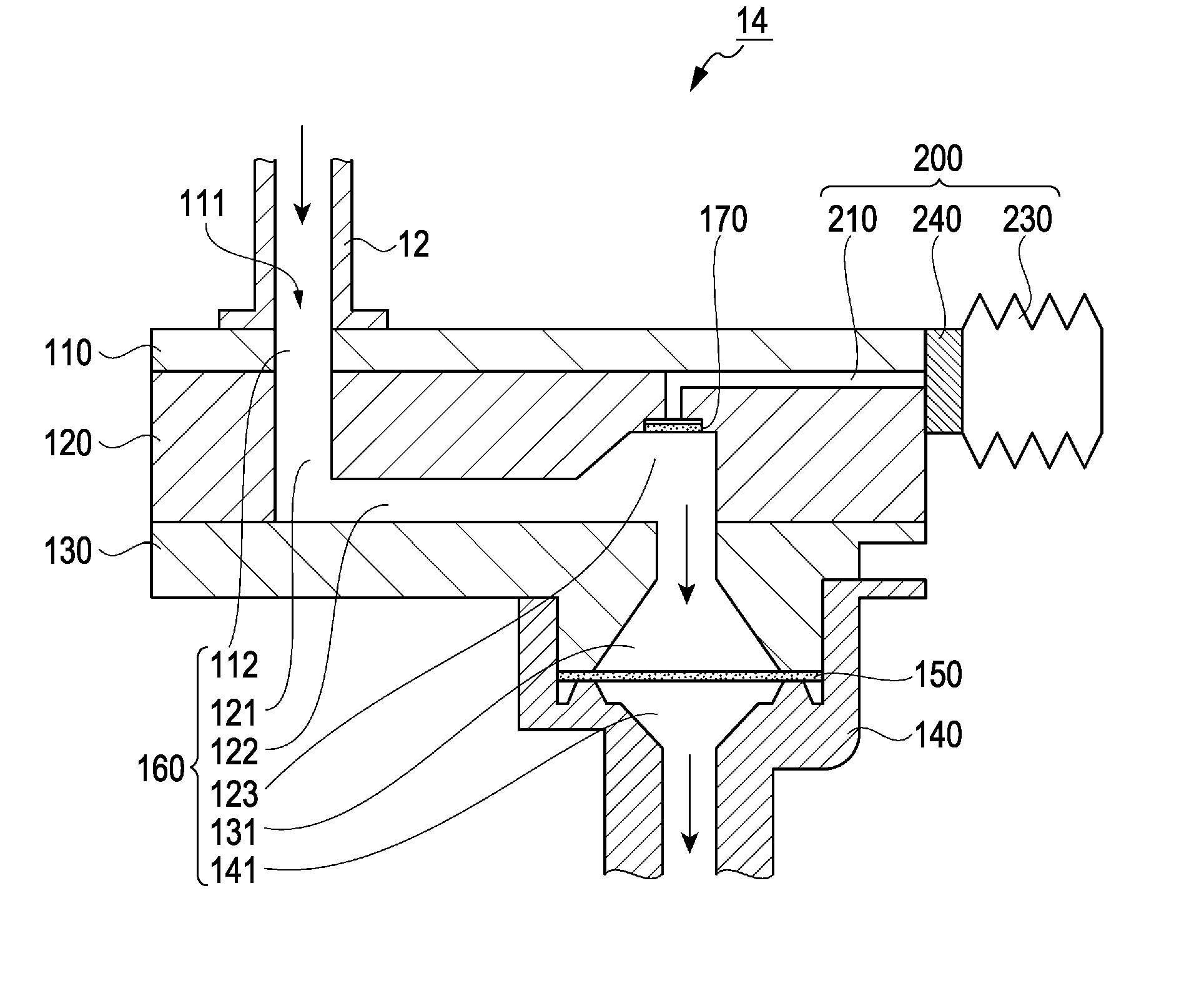
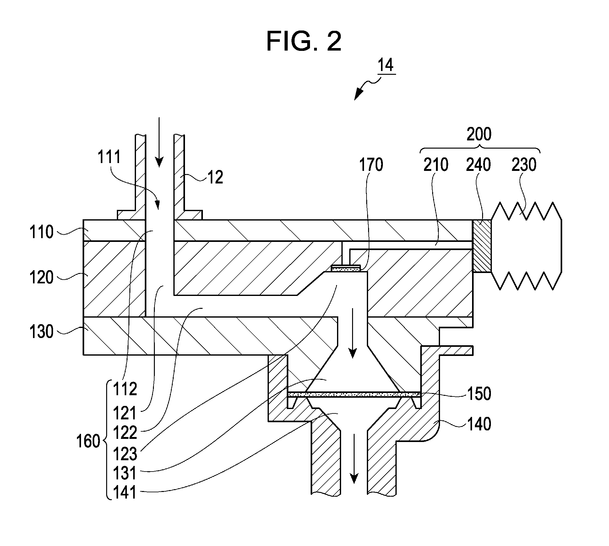
[0075]Although in the above embodiment, a flow path sectional area of the merge path 220 is constant, a narrowed portion 221 having a reduced flow path sectional area may be disposed in the merge path 220 as shown in FIG. 7. With this configuration, since the narrowed portion 221 serves as a flow path resistance, it is possible to prevent ink thickening due to volatilization of ink in the air bubble trap 123 via the waterproof member 170, the first path 211, the merge path 220, the second path 212, the pump member 230, and the atmosphere opening path 243. Further, since the narrowed portion 221 serves as a flow path resistance, suctioning of air bubbles is gradually performed over a longer period of time with the same amount of expansion and contraction of the pump member 230. Accordingly, air bubbles can be more effectively suctioned by adjusting the amount and duration of suction force to suction air bubbles by appropriately designing the form of the narrowed portion 221.

second modified example

[0076]Although in the above embodiment, one waterproof member 170 is provided for each of the four air bubble traps 123, a plurality of waterproof members 170 may be provided for each air bubble trap 123. For example, in the case where air bubbles tend to be collected at the corners of chamber that forms the air bubble trap 123, the waterproof members 170 may be provided for each corner of the air bubble trap 123. With this configuration, air bubbles collected in the air bubble trap 123 can be more effectively discharged.

third modified example

[0077]Although in the above embodiment, a portion of the distribution flow path 160 which expands vertically upward serves as the air bubble trap 123, the configuration of the air bubble trap 123 is not limited thereto. For example, as shown in FIG. 8A, an upper side of a portion of the distribution flow path 160 which expands vertically downward may serve as the air bubble trap 123. Further, an expanded portion may not be provided, and in the case where distribution flow path 160 has no expanded portion, the outer corner of the bend of the flow path in which air bubbles tend to be collected may serve as the air bubble trap 123 as shown in FIG. 8B.


PUM


Abstract

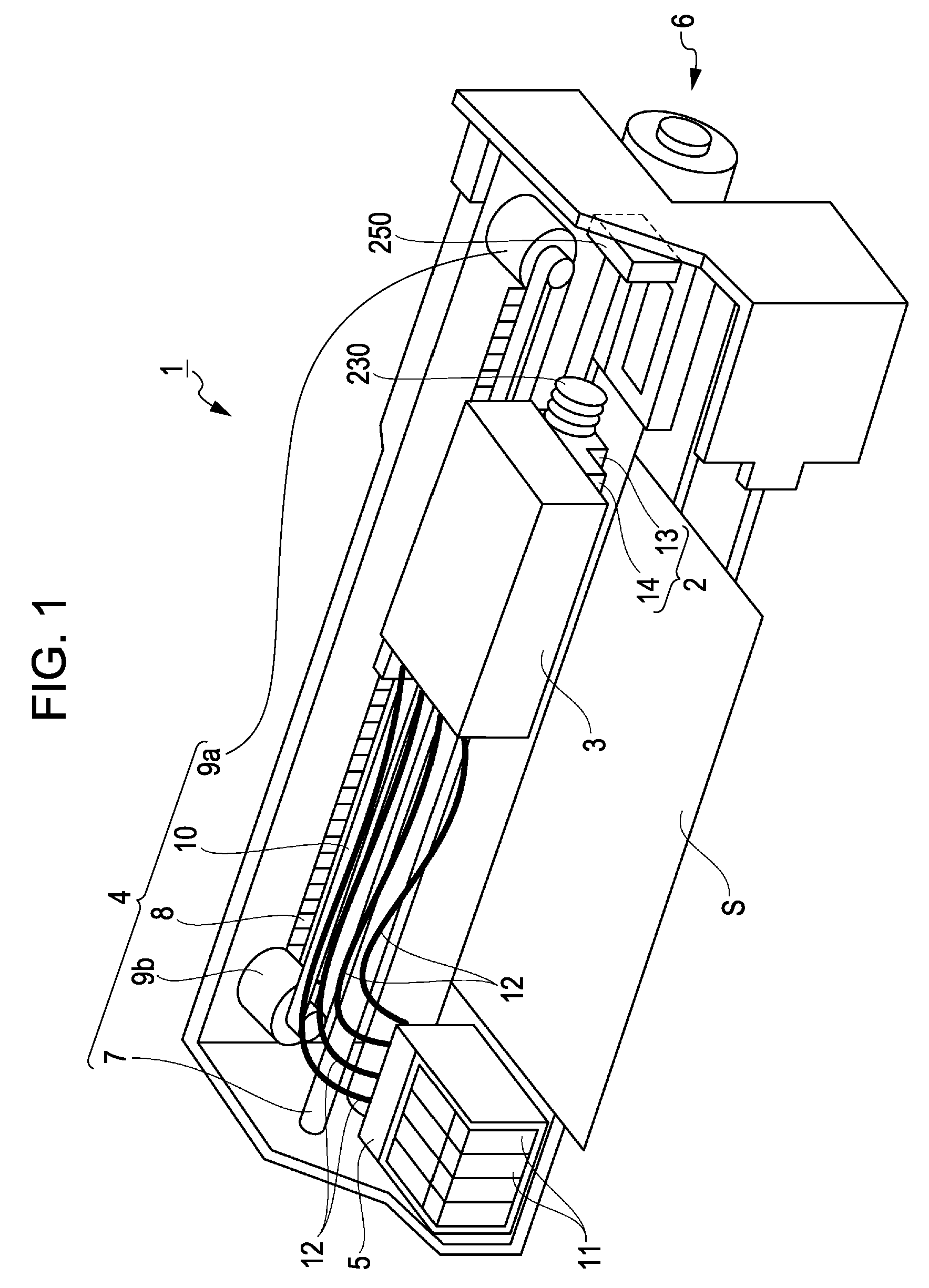
A printer includes a filter unit having a distribution flow path through which the introduced ink flows into a recording head, and an air bubble trap in which air bubbles which have entered ink in the distribution flow path are collected, the air bubble trap being provided with a waterproof member having a waterproof property and an air permeability that forms part of a wall of the air bubble trap. A printer includes an air bubble suction mechanism that suctions air bubbles collected in the air bubble trap through the waterproof member.

Description

BACKGROUND[0001]1. Technical Field[0002]The present invention relates to a liquid ejection apparatus having a liquid ejection head that ejects a liquid.[0003]2. Related Art[0004]As an example of liquid ejection apparatus, ink jet printers having a recording head, which is an example of a liquid ejection head, are well known. In the ink jet printers, ink is supplied from a liquid containing chamber such as an ink cartridge to a recording head via a flow path formed in a flow path forming member. Once supplied to the recording head, ink is stored in a reservoir, and then supplied from the reservoir to pressure generating chambers. When pressure generating elements such as piezoelectric elements apply pressure change to ink in the pressure generating chambers, ink is ejected through nozzles that communicate with the pressure generating chambers.[0005]In such an ink jet printer, if air bubbles are present in the flow path due to air bubbles previously contained in ink which is introduce...

Claims


Application Information

Patent Timeline
Patent Type & Authority Patents(United States)
IPC IPC(8): B41J2/19
CPCB41J2/19B41J2/175B41J2/14274
Inventor HANAGAMI, TAIKI
Owner SEIKO EPSON CORP
Learn More