
Dispensing method

a technology of dispensing method and liquid chamber, which is applied in the direction of liquid dispensing, combustion process, lighting and heating apparatus, etc., can solve the problems of micropumps being produced in liquid, surface tension effect may impair the perfect function of such micropumps, and micropumps are very liable to fault, etc., to achieve the effect of reducing cleaning time, facilitating cleaning, and reducing cleaning tim

Active Publication Date: 2008-06-03
EVOTEC
View PDF7 Cites 0 Cited by
  • Summary
  • Abstract
  • Description
  • Claims
  • Application Information

AI Technical Summary

Benefits of technology

[0008]According to the invention, the medium in the liquid chamber of the liquid delivery device, i.e., particularly the liquid and existing impurities, are vibrated during the cleaning step in which the liquid chamber is flushed. By vibrating the medium, it is possible to act upon impurities, particularly gas bubbles, existing in the liquid chamber in such a manner that they disintegrate. Impurities which may be both particles and gas bubbles disintegrate into smaller parts and smaller bubbles, respectively. These can be flushed out of the liquid chamber more easily. Thereby, for example, a gagging of the nozzle because of relatively large impurities is avoided if the liquid delivery device is a dispensing or pipetting device. By vibrating the medium located in the liquid chamber and the disintegration of the impurities, particularly the gas bubbles, caused thereby, they can be flushed out of the liquid chamber more easily. The method according to the invention is particularly suitable for flushing out gas bubbles which cannot be flushed out or only difficulty so by means of known flushing methods since gas bubbles adhere to the surfaces of the dispensing device. Thus, the liquid chamber can be cleaned faster. This is a particular great advantage with automatic methods such as the medium or high throughput screening. Thus, it is possible by means of the method according to the invention to considerably reduce the cleaning times. Further, the reliability is increased by the method according to the invention since larger impurities disintegrate and c an thus be reliably removed from the liquid chamber. Furthermore, the consumption of liquid in a cleaning step is considerably reduced. This is particularly advantageous with dispensing devices in which the cleaning is effected by means of sample liquid.
[0009]In a particularly preferred embodiment of the invention, the frequency of the vibrations occurring in the liquid is varied during a cleaning step. To this end, the frequency of a pulse generator acting upon the liquid is varied, the variation of the frequency of the pulse generator provoking a variation of the vibration frequency of the medium. It is particularly preferred if a piezo actuator or a corresponding component is used as a pulse generator to this end. If the liquid delivery device is a dispensing or pipetting device, it is particularly preferred to use the pulse generator such as, for example, the piezo actuator, by which the drop delivery is caused, as a pulse generator for generating the vibrations in the liquid as well. This has the advantage that no additional component is required to perform the cleaning step including the flushing of the liquid chamber and the vibrating of the medium according to the invention.
[0010]Varying the vibrational frequency has the advantage that impurities or gas bubbles of different sizes can be resonated whereby the disintegration process is triggered. Thus, varying the frequency results in a further reduction of the flushing times. This increases the reliability of the liquid delivery device and reduces the liquid amount required for flushing. This is particularly advantageous with medium and high throughput screening. The frequency or the different frequencies which are produced during a cleaning step can be advantageously selected, for example, in dependence on the used liquid and the danger of larger or smaller agglomerates resulting therefrom, for example. The frequencies can also be matched to the fact that a liquid has a stronger or weaker tendency to develop gas and thus forms gas bubbles.
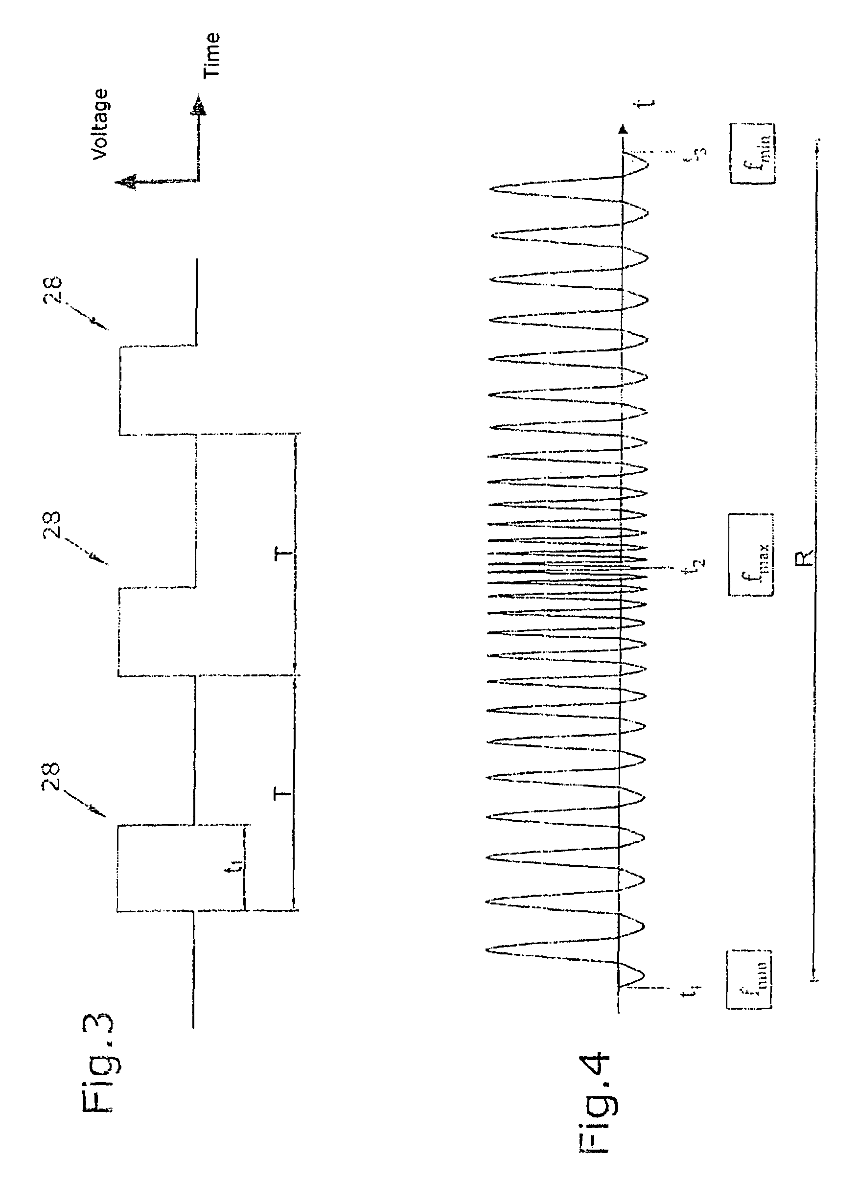
[0011]Experiments have shown that a minimum frequency of at least 1 kHz, preferably at least 3 kHz, is particularly advantageous when gas bubbles occur. Very good results can further be achieved when the maximum frequency amounts to 60 kHz at maximum, preferably 40 kHz at maximum. Within the minimum frequency and the maximum frequency, the frequency is changed continuously or stepwise. Good cleaning results can be achieved when the frequency is increased stepwise by 200-250 Hz per step. Starting from a minimum frequency, the frequency is preferably increased toward the maximum frequency. Since larger bubbles disintegrate into smaller and smaller bubbles and particles disintegrate into smaller and smaller particles, respectively, it is advantageous to increase the frequency to a maximum frequency starting from the minimum frequency for the disintegration into bubbles or particles which are as small as possible and adapted to be flushed out can be accelerated. If necessary, changes between individual frequencies are possible so that the frequencies are repeatedly increased and decreased during one cleaning step. Furthermore, a combination of both processes is possible.

Problems solved by technology

In principle, micropumps are very liable to fault.
Furthermore, surface tension effects may impair the perfect function of such micropumps.
One problem which often occurs with micropumps, e.g., is that precipitations, e.g. of crystallizations of the liquid in the liquid chamber, are produced within the liquid chamber.
This often results in a failure of the micropump.
With micropumps used in dispensing and pipetting devices, gas bubbles at least lead to a falsification of the delivered drop size and thus to a falsification of the delivered liquid amount if they will not directly result in the failure of the micropump.
Such known flushing methods, however, are time-consuming.
This is particularly disadvantageous if such liquid delivery devices are used in medium or high throughput screening.
Further, the liquid consumption in known flushing methods is extremely high.
This is particularly disadvantageous when the flushing in a dispensing device has to be done with expensive sample liquid.

Method used


Image

  • Dispensing method
  • Dispensing method
  • Dispensing method

Examples


Embodiment Construction

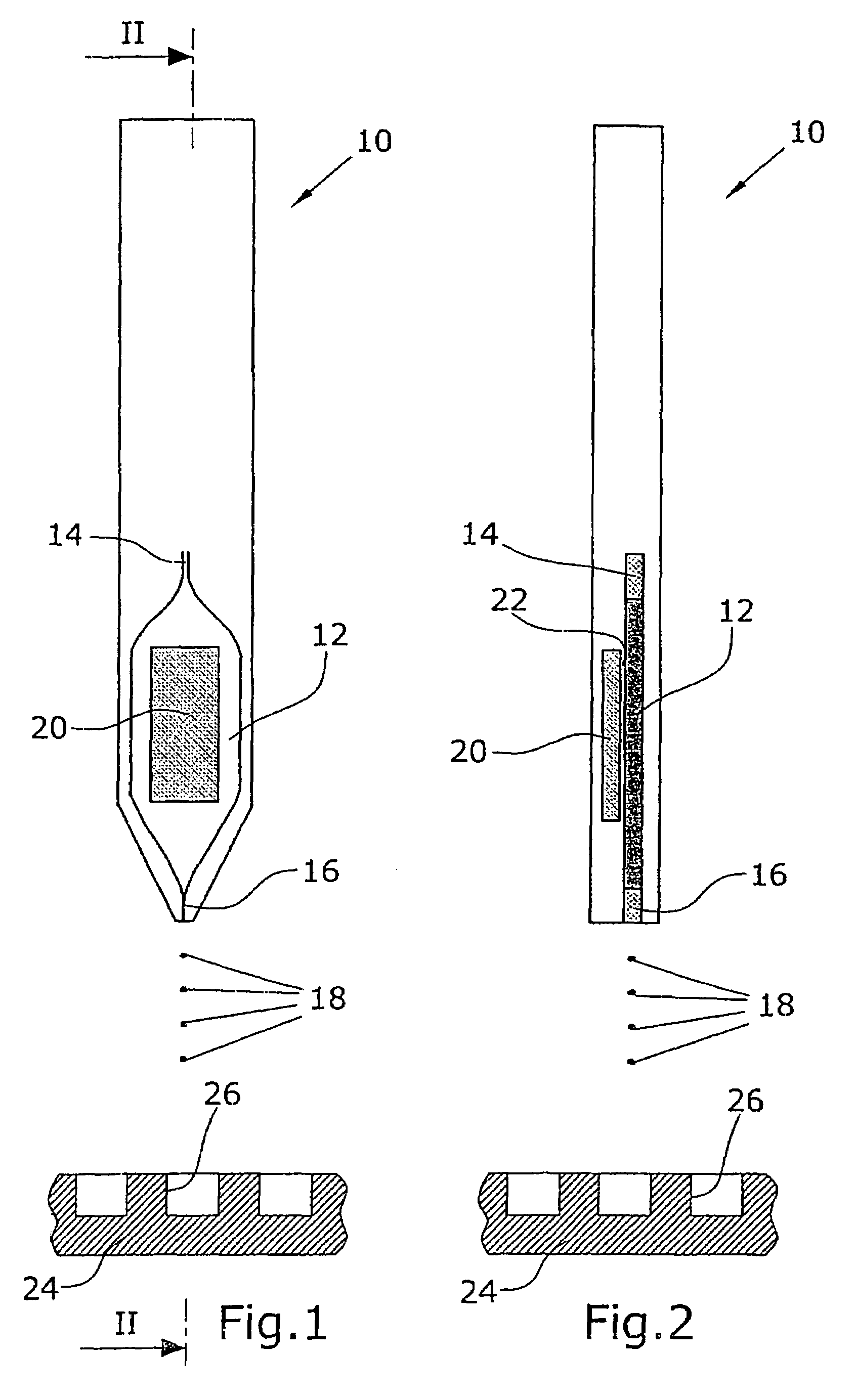
[0017]The liquid delivery device 10 illustrated in FIGS. 1 and 2 is, e.g., a dispensing device. It comprises a liquid chamber 12 connected with a reservoir via a channel 14. In a dispensing device, the reservoir contains the sample liquid dispensed in the form of drops 18 through a nozzle or the capillary channel 16. If necessary, the liquid chamber 12 is further connected with another reservoir containing flushing liquid for performing a cleaning step. A piezo actuator 20 acts upon the liquid in the liquid chamber 12. The piezo actuator 20 acts upon an elastic wall 22 of the liquid chamber 12. By applying a voltage to the piezo actuator 20, the elastic wall 22 is deformed and a pressure pulse is exerted upon the liquid in the liquid chamber 12. Thereby, a drop 18 is delivered, e.g., toward a microtiter plate 24 for filling wells 26 located in the microtiter plate 24.

[0018]The excitation pulse form shown in FIG. 3 is a possible voltage pulse sequence applied to the piezo actuator 20...


PUM

PropertyMeasurementUnit
frequencyaaaaaaaaaa
frequencyaaaaaaaaaa
volumeaaaaaaaaaa

Abstract

In a method for cleaning a liquid delivery device such as a dispensing or pipetting device, the liquid chamber can be flushed in a cleaning step. To remove gas bubbles which might exist in the liquid chamber, for example, the liquid in the liquid chamber is vibrated during the cleaning step.

Description

FIELD OF THE INVENTION[0001]The invention relates to a dispensing method for dispensing chemical and / or biological liquids in minimum amounts by means of a liquid delivery device, particularly a micropump in a dispensing and / or pipetting device and / or other microsystems.DISCUSSION OF THE BACKGROUND ART[0002]For dispensing and pipetting very small liquid amounts in the range of a few pl to μl, micropumps, for example, are utilized as a liquid delivery device, which eject drops through a nozzle of the dispensing or pipetting device. As a micropump, such dispensing or pipetting devices comprise a liquid chamber that contains a sample liquid or a system liquid. A wall of the sample chamber is configured to be, e.g., elastic, particularly as a diaphragm. A pulse generator such as a piezo actuator acts upon the elastic wall. Pressure pulses can be generated in the liquid chamber by the piezo actuator. They cause a delivery of liquid drops from the nozzle. The droplet volume is clearly def...

Claims


Application Information

Patent Timeline
Patent Type & Authority Patents(United States)
IPC IPC(8): B05B17/06B05B1/08B05B15/02B05B17/04B65D47/18B01L3/02B01L99/00G01N35/10
CPCB01L3/0268G01N35/1004B01L99/00B01L2400/0439B01L13/02
Inventor WENDT, OLIVERPRECKEL, HARTWIG
Owner EVOTEC
Learn More