Fuel cell module

a fuel cell module and module technology, applied in the field of fuel cell modules, can solve the problems of high cost of heat insulation, high production cost, and significant increase in heat radiation from the fuel cell in a thermally insulated state, and achieve the effect of reducing heat radiation from the fuel cell module, suppressing radiation, and reducing heat radiation

Inactive Publication Date: 2013-12-03
HONDA MOTOR CO LTD
View PDF12 Cites 0 Cited by
  • Summary
  • Abstract
  • Description
  • Claims
  • Application Information

AI Technical Summary

Benefits of technology

[0013]The present invention has been made to solve the problem of this type, and an object of the present invention is to provide a fuel cell module which makes it possible to prevent heat from excessively being released from a heat generating portion, achieve reduction in the heat insulating capacity and the production cost, facilitate thermally self-sustained operation, and improve the heat efficiency.
[0016]In the present invention, the fuel cell module is surrounded by a plurality of heat insulating layers including an inner heat insulating layer and an outer heat insulating layer, and the inner heat insulating layer contains a large amount of metal component in comparison with the outer heat insulating layer. In the structure, the inner heat insulating layer containing the large amount of metal component can suppress radiation of heat from the high temperature area, and the outer heat insulating layer having the small amount of metal component can suppress heat conductance in the low temperature area. Thus, in the inner heat insulating layer and the outer heat insulating layer, it is possible to achieve the optimum heat insulation in the respective temperature areas. It is possible to reliably achieve reduction of heat radiation from the fuel cell module, facilitate thermally self-sustaining operation, improve the heat efficiency, reduce the volume in the heat insulating layer, and reduce the production cost.

Problems solved by technology

Further, heat insulating capacity (volume) for containing the solid oxide fuel cell in a thermally insulated state becomes significantly large, and the cost for heat insulation becomes high.
Therefore, the fuel cell reforming system has complicated structure, and the production cost becomes high.
Further, since the inner heat insulating material 5a and the outer heat insulating material 6a do not have different capabilities depending on the functions of the units to be covered, improvement in the overall heat efficiency in the reforming system cannot be achieved.
Further, though the relationship of the heat conductance between the casing body 6b and the heat insulating layer 7b is disclosed, in particular, it is not possible to suppress heat radiation from the high temperature apparatus.
Therefore, in particular, it is not possible to suppress radiation of heat from the reformer 6c and the combustor 7c, and reduction in the heat insulating capacity cannot be reduced.

Method used


Image

  • Fuel cell module
  • Fuel cell module
  • Fuel cell module

Examples


first embodiment

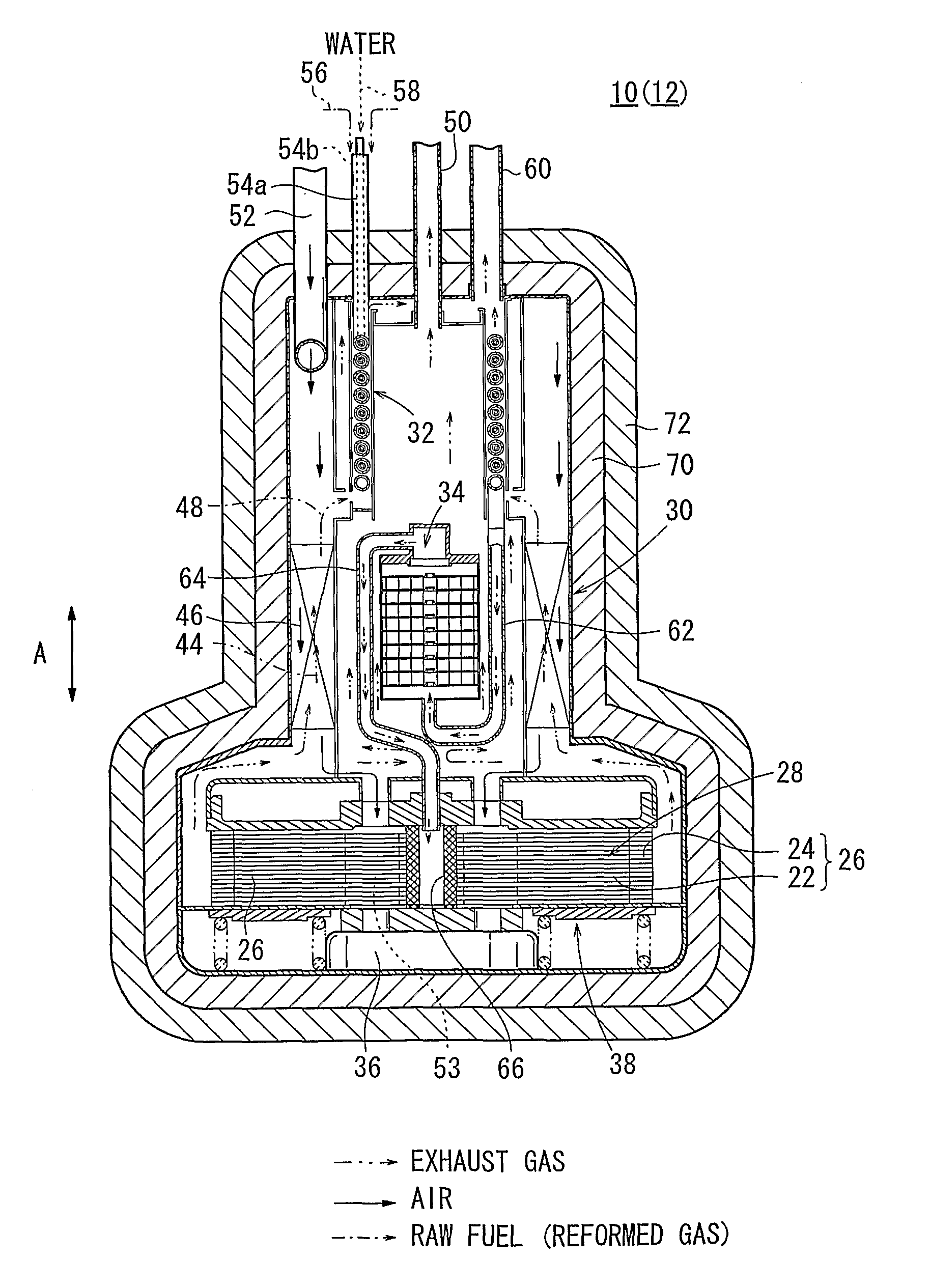
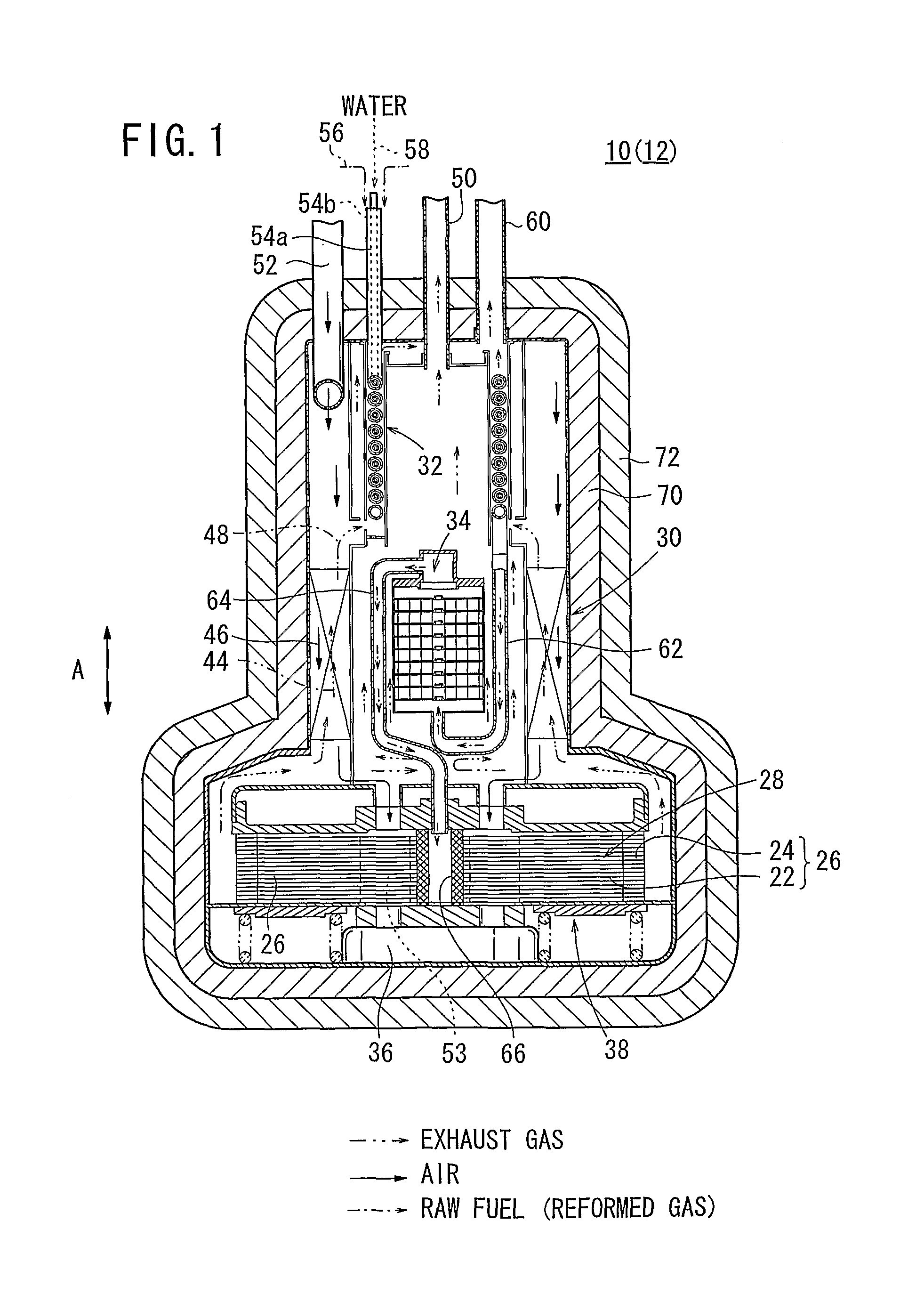
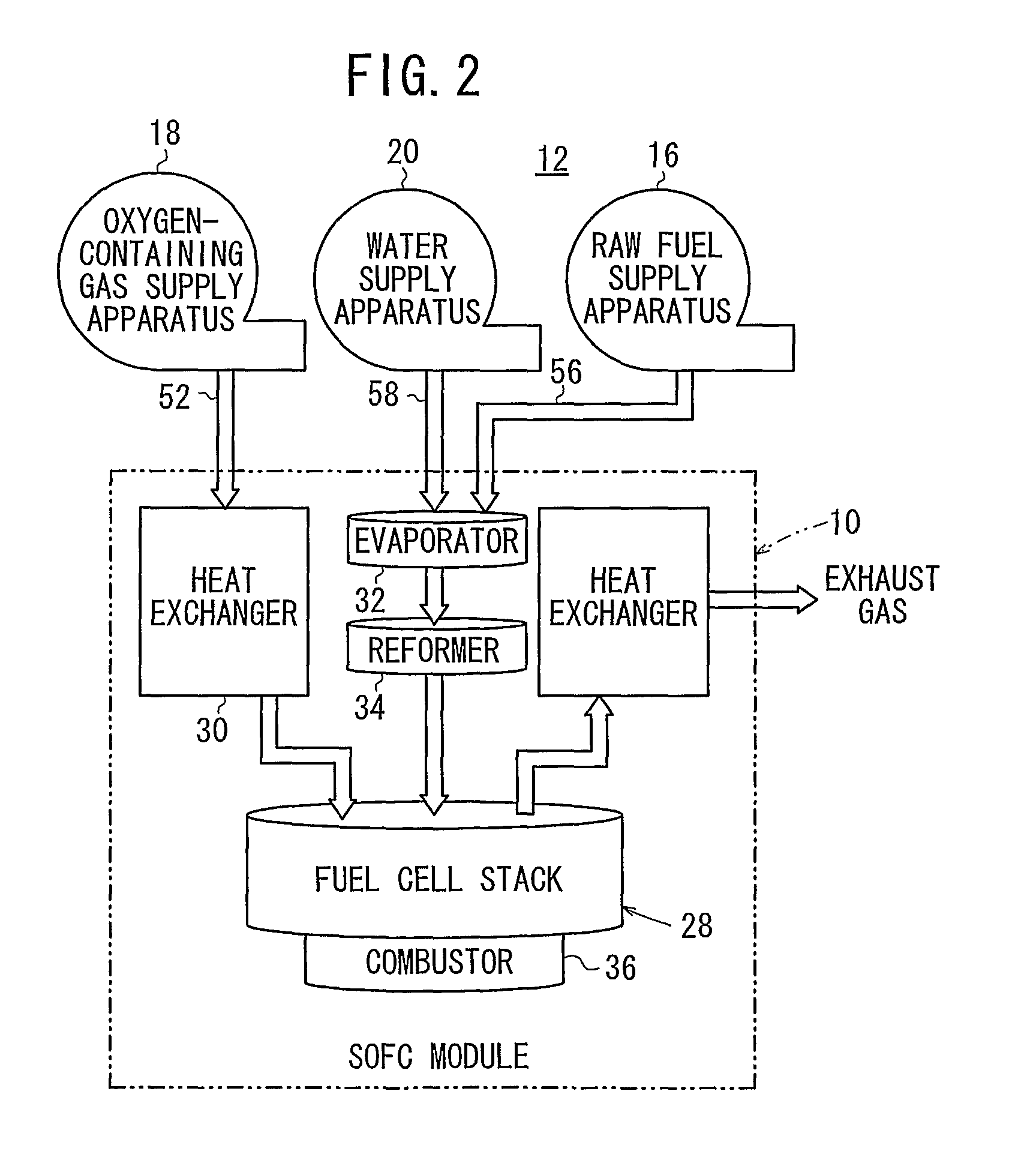
[0028]FIG. 1 is a cross sectional view showing a fuel cell module 10 according to the present invention. FIG. 2 is a diagram schematically showing structure of a mechanical circuit of a fuel cell system 12 including the fuel cell module 10.

[0029]The fuel cell system 12 is used in various applications, including stationary and mobile applications. For example, the fuel cell system 12 is mounted on a vehicle. The fuel cell system 12 includes a fuel cell module (SOFC module) 10 for generating electrical energy in power generation by electrochemical reactions of a fuel gas (hydrogen gas) and an oxygen-containing gas (air), a raw fuel supply apparatus (including a fuel gas pump) 16 for supplying a raw fuel (e.g., city gas) to the fuel cell module 10, an oxygen-containing gas supply apparatus (including an air pump) 18 for supplying an oxygen-containing gas to the fuel cell module 10, and a water supply apparatus (including a water pump) 20 for supplying water to the fuel cell module 10.

[...

second embodiment

[0053]In the second embodiment, the metal plating layer 82 is provided around the fuel cell module 80. Therefore, by the metal plating layer 82, it is possible to further suppress radiation of heat from the high temperature area.

[0054]In the second embodiment, the fuel cell module 80 is surrounded by three insulating layers, i.e., the metal plating layer 82, the inner heat insulating layer 70, and the outer heat insulating layer 72. However, the present invention is not limited in this respect. For example, four or more heat insulating layers may be provided.

third embodiment

[0055]FIG. 5 is a cross sectional view showing a fuel cell module 90 according to a

[0056]The fuel cell module 90 is surrounded by the inner heat insulating layer 70, the outer heat insulating layer 72, and a fluid channel 92 is formed between the inner heat insulating layer 70 and the outer heat insulating layer 72. Fluid which can absorb radiation of heat from the fuel cell module 90 such as the air (oxygen-containing gas) flows into the fluid channel 92 from a channel inlet 94 before the oxygen-containing gas is supplied to the heat exchanger 30.

[0057]The fluid channel 92 may be provided around the entire circumference of the fuel cell module 90. Alternatively, a plurality of separate fluid channels 92 may be provided. An air pipe 52a is connected to upper portion of the fluid channel 92. The air pipe 52a is connected to the air channel 46 of the heat exchanger 30.

[0058]In the third embodiment, the air flowing through the fluid channel 92 can effectively absorb heat which has not ...


PUM

PropertyMeasurementUnit
operating temperatureaaaaaaaaaa
heat insulatingaaaaaaaaaa
heataaaaaaaaaa

Abstract

A fuel cell module includes a fuel cell stack, a heat exchanger, an evaporator, a reformer, and a combustor for at least heating any of the fuel cell stack, the heat exchanger, the evaporator, and the reformer. The fuel cell module is surrounded by an inner heat insulating layer and an outer heat insulating layer. The inner heat insulating layer is used in a high temperature area, and the outer heat insulating layer is used in a low temperature area. The inner heat insulating layer contains a large amount of metal component in comparison with the outer heat insulating layer.

Description

RELATED APPLICATIONS[0001]This application is a 35 U.S.C. 371 national stage filing of International Application No. PCT / JP2008 / 069170, filed Oct. 16, 2008, which claims priority to Japanese Patent Application No. 2007-271054 filed on Oct. 18, 2007 in Japan. The contents of the aforementioned applications are hereby incorporated by reference.TECHNICAL FIELD[0002]The present invention relates to a fuel cell module including a fuel cell stack, a heat exchanger, an evaporator, a reformer, and a combustor. The fuel cell stack is formed by stacking a plurality of fuel cells. The heat exchanger heats an oxygen-containing gas before the oxygen-containing gas is supplied to the fuel cell stack. The evaporator produces a mixed fuel of a raw fuel chiefly containing hydrocarbon and water vapor obtained by evaporating water. The reformer produces a reformed gas by reforming the mixed fuel. The combustor at least heats any of the fuel cell stack, the heat exchanger, the evaporator, and the refor...

Claims


Application Information

Patent Timeline
Patent Type & Authority Patents(United States)
IPC IPC(8): H01M8/02H01M8/04H01M8/10
CPCH01M8/04007H01M8/12H01M8/2475H01M2008/1293Y02E60/521Y02E60/525Y02P70/50Y02E60/50
Inventor YAMAMOTO, JUNSAITO, BUNICHIKIYOHIRO, YUKIHIKODAN, KOJIHOMMA, HIROKI
Owner HONDA MOTOR CO LTD
Why Eureka
Try Eureka