Power strip hanging device and structure

a technology of power cords and hanging devices, which is applied in the direction of washstands, lighting support devices, coupling devices, etc., can solve the problems of long time to connect plugs, limited number of inability to directly connect power cords of electronic devices to the floor or wall sockets

Active Publication Date: 2013-12-03
RITE TECH INDAL
View PDF9 Cites 18 Cited by
  • Summary
  • Abstract
  • Description
  • Claims
  • Application Information

AI Technical Summary

Benefits of technology

[0006]In view of the aforementioned drawbacks of the conventional power strips, the inventor of the present invention conducted extensive research and experiment and finally succeeded in developing a power strip hanging device and structure as disclosed herein. The disclosed power strip hanging device and structure are intended to prevent a power strip from being inadvertently kicked as is often the case when it is placed on the floor. The disclosed hanging device and structure are also intended to allow rapid storage of the power strip after use, so that the power strip will not occupy or mess up the space on the tabletop.
[0007]It is an object of the present invention to provide a power strip hanging device including a hanging element. The hanging element includes a hanger body and a cover. The cover is provided with an insertion plug corresponding in configuration to the sockets of a power strip so as to be inserted into the sockets. The hanger body has an end defining an end surface, wherein the end surface is provided with a pulling portion to be pulled by the user. In addition, a shoulder extends outward from the periphery of the aforesaid end of the hanger body. The hanger body and the cover can be connected as a single piece, thereby fixing the hanging element securely at one end of the power strip. The hanging element and the power strip can pass through an installation hole of a table at the same time so that the shoulder of the hanging element rests on the rim of the installation hole. Thus, the power strip having passed through the installation hole is secured under the table. The structural features of the present invention are such that the user only has to connect the hanging element to one end of the power strip, and the power strip can be hung and positioned under the table without occupying or messing up the space on the tabletop. When it is desired to use the power strip, the user can pull the pulling portion to not only draw the hanging element out of the installation hole, but also pull the power strip out on the tabletop, thus allowing a plurality of electronic apparatuses to plug into the power strip. Hence, the present invention substantially increases the convenience of use of the power strip.
[0008]It is another object of the present invention to provide the foregoing power strip hanging device, wherein the power strip hanging device further includes a positioning seat. The positioning seat has an upper opening on one side and a lower opening on the opposite side. The upper opening and the lower opening communicate with each other and form a receiving space in the positioning seat. Also, the positioning seat is externally provided with a positioning portion that extends outward. The outer configuration of the positioning seat matches the aforesaid installation hole so that the positioning seat can be fixed to the hole wall of the installation hole and be positioned firmly in the installation hole, with the positioning portion resting on the table. In addition, the outer configuration of the hanging element matches the upper opening so that the hanging element can pass through the upper opening and be received in the receiving space of the positioning seat, with the shoulder resting on the rim of the upper opening of the positioning seat. Thus, the hanging element is supported by the positioning seat, and the power strip connected with the hanging element and having passed through the positioning seat is secured under the table.

Problems solved by technology

However, floor or wall sockets are always limited in number.
Moreover, the power cords of the electronic apparatuses may be too short to be directly connected to the floor or wall sockets.
In that case, when it is desired to plug the electronic apparatuses into the power strip, the users must go under the table to make the connections, which is very inconvenient.
Since the area under the conference table is usually insufficiently lit, it may take a long time to connect the plugs to the power strip, which not only wastes the users' precious time but also causes unnecessary troubles.
Furthermore, the users may inadvertently kick the power strip or the plugs under the table such that the plugs come off the power strip.
Should this happen, in addition to the inconveniences caused, the electronic apparatuses could be damaged by the sudden power outage, which is highly undesirable.
Nevertheless, when the power strip is no longer in use, it still occupies certain space on the tabletop, if not making the table untidy.

Method used


Image

  • Power strip hanging device and structure
  • Power strip hanging device and structure
  • Power strip hanging device and structure

Examples


Embodiment Construction

[0022]The inventor of the present invention has long been engaged in the research and development of power strips and has hence found that the conventional power strips tend to occupy too much space on a tabletop when not in use and may render the tabletop untidy. The industry has tried to overcome the aforesaid problems by improving the conventional power strips, but an ideal solution has yet to be found. In consideration of the above, the inventor came up with the idea of putting a power strip away by hanging and securing it in an installation hole of a table, thereby solving the problem of the conventional power strips that they tend to take up too much space when not in use.

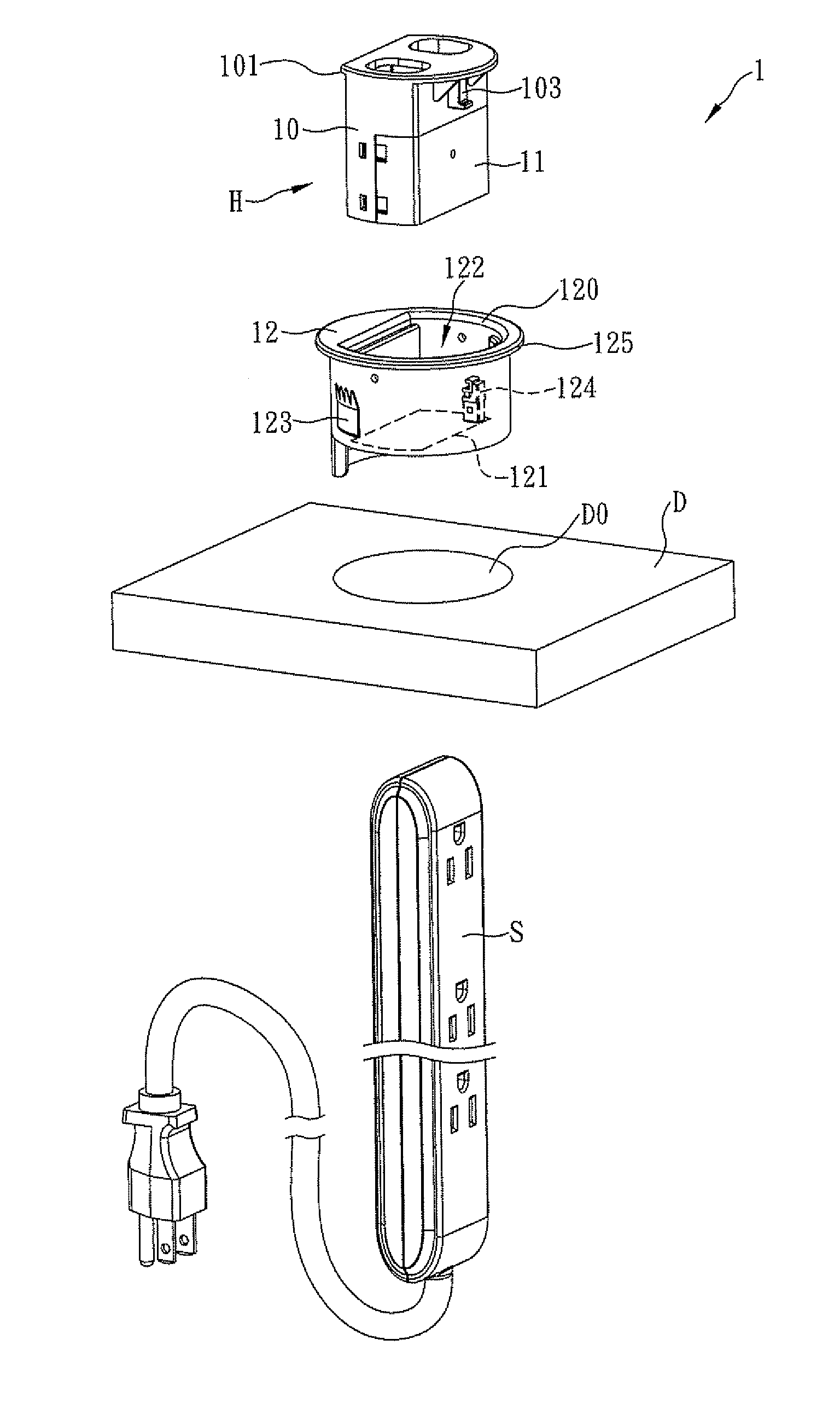
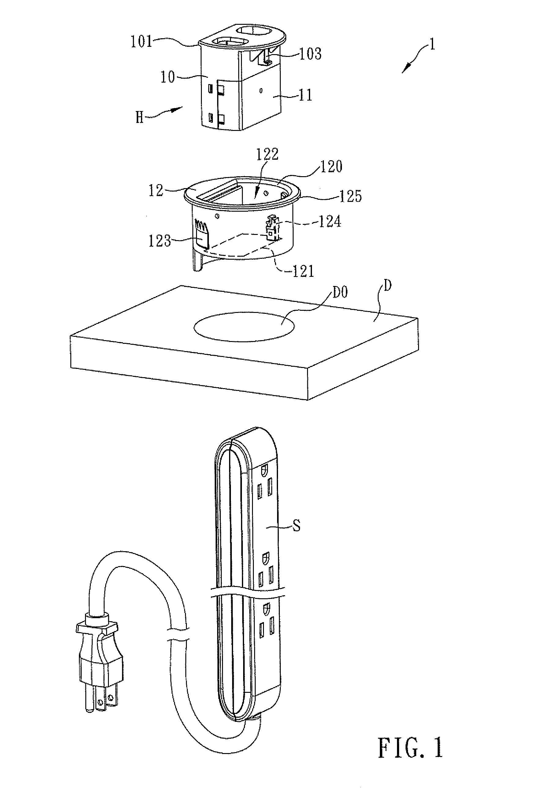
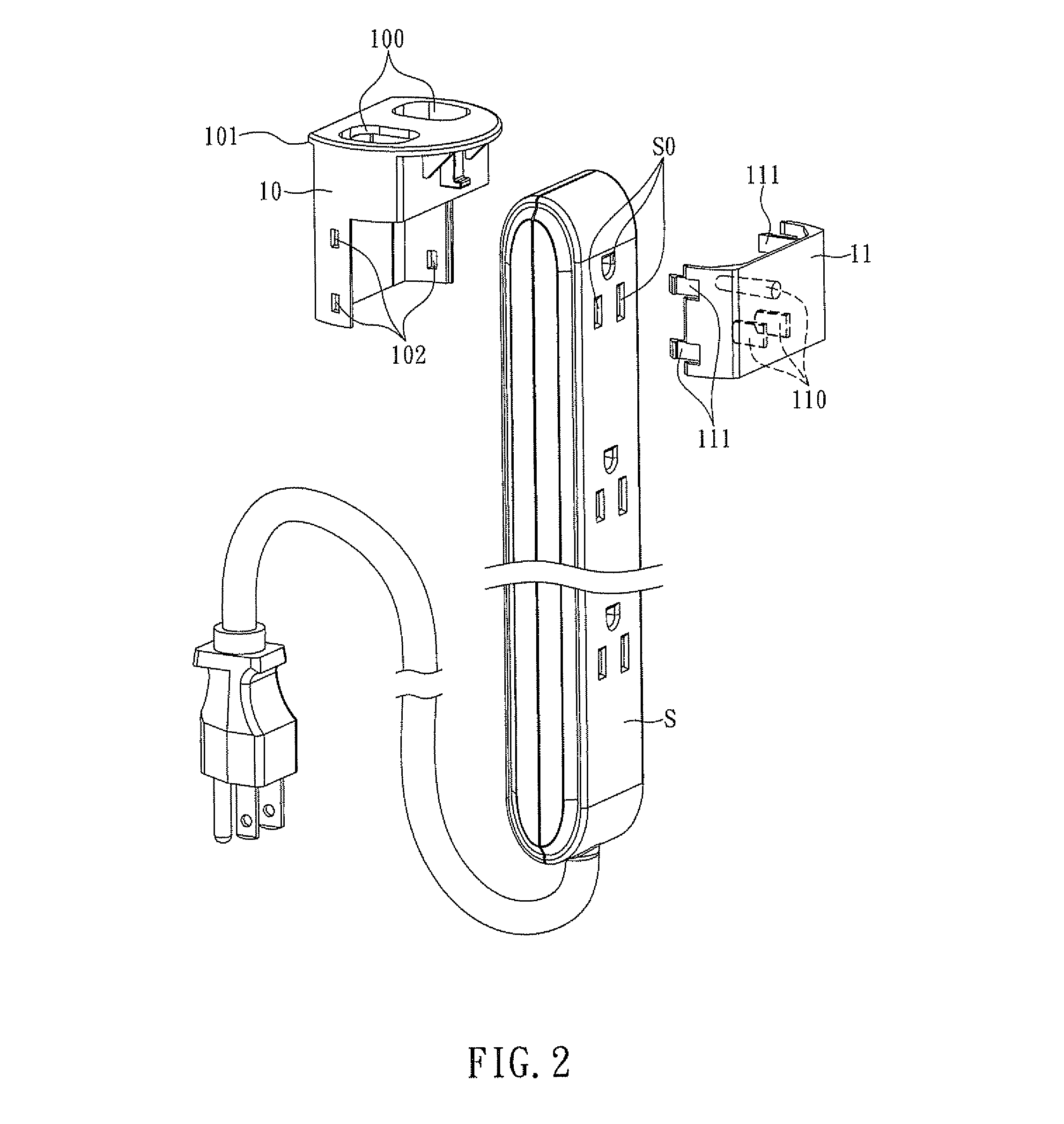
[0023]The present invention provides a power strip hanging device and structure. Referring to FIG. 1, a power strip hanging device 1 according to the first preferred embodiment of the present invention includes a hanging element H and a positioning seat 12. The hanging element H includes a hanger body 10 and ...


PUM


Abstract

A power strip hanging device and structure are provided. The hanging device includes a hanger element and a positioning seat. The hanger element has a pulling portion for being pulled by a user and a shoulder extended outward from the periphery of one end thereof. The positioning seat has an upper opening on one side and a lower opening on the opposite side communicating with the upper opening to form a receiving space therein, and is positioned firmly in an installation hole of a table, so that the hanging element can pass through the upper opening and be received in the receiving space with the shoulder resting on the rim of the upper opening. Thus, the hanging element is supported by the positioning seat, and the power strip can pass through the positioning seat and be secured under the table without occupying the space on a top of the table.

Description

FIELD OF THE INVENTION[0001]The present invention relates to a power strip hanging device and structure, more particularly to a hanging element having an insertion plug inserted into sockets of a power strip and having a shoulder extended outward from the periphery of one end thereof, so that the shoulder of the hanging element is able to rest on the rim of an installation hole of a table, and allow the power strip to pass through the installation hole and be hung and positioned under the table without occupying or messing up the space on a top of the table.BACKGROUND OF THE INVENTION[0002]Electronic apparatuses such as computers, projectors, and printers have become indispensable tools for work due to their declining prices and continuously improved performances (e.g., higher computing speed, higher image clarity, etc.). One may even have to use several computers and other electronic apparatuses simultaneously in the workplace. While some electronic apparatuses (e.g., laptop comput...

Claims


Application Information

Patent Timeline
Patent Type & Authority Patents(United States)
IPC IPC(8): H01H9/02
CPCH02G3/185A47B2200/0082
Inventor HSIAO, FENG-HSIU
Owner RITE TECH INDAL
Why Eureka
Try Eureka