Devices and methods for fluorescent inspection and/or removal of material in a sample

a technology of fluorescent inspection and/or material removal, which is applied in the direction of diagnostic recording/measuring, instruments, therapy, etc., to achieve the effect of facilitating identification and retrieval

Inactive Publication Date: 2007-11-22
UNIV OF UTAH RES FOUND +1
View PDF21 Cites 32 Cited by
  • Summary
  • Abstract
  • Description
  • Claims
  • Application Information

AI Technical Summary

Benefits of technology

[0100]In a second aspect, the fluorescent cobalamins are used to identify atypical cells such as neoplastic cells, dysplastic cells, or hyperplastic cells. More particularly, the fluorescent cobalamins are used to distinguish cancer cells from healthy cells. In one embodiment, a fluorescent cobalamin is administered to a patient prior to, or during, surgery. The presence of fluorescence, phosphorescence, luminescence or emitted light in cancer cells is used by the surgeon to define the tissue to be removed, whether in a primary tumor or in a m...

Problems solved by technology

This procedure is controversial, as it fails t...

Method used


Image

  • Devices and methods for fluorescent inspection and/or removal of material in a sample
  • Devices and methods for fluorescent inspection and/or removal of material in a sample
  • Devices and methods for fluorescent inspection and/or removal of material in a sample

Examples


Embodiment Construction

[0024]The present invention relates generally for systems for detection and removal using fluorescent, phosphorescent, or emitted light.

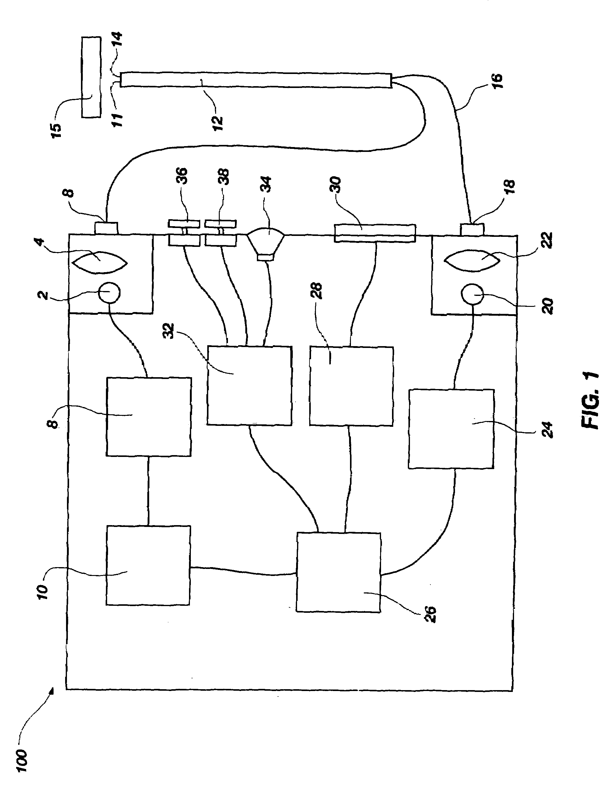
[0025]Referring now to drawing FIG. 1, there is illustrated a schematic view of one example of an embodiment of an apparatus according to the present invention generally at 100. As illustrated, the apparatus 100 includes light emitting component 2 that is used to generate light capable of stimulating a fluorescent, phosphorescent, or luminescent emission from a target light emitting material. The emission of light by light emitting component 2 is controlled by driver 8, which is configured to control the flow of electrical power to light emitting component 2. In this way, driver 8 controls when light emitting component 2 is providing light to excitation optical fiber 6. Driver 8 is in turn controlled by frequency generator 10. Frequency generator 10 controls the illumination of light emitting component 2 through driver 8, resulting in the modulation...


PUM


Abstract

An apparatus is provided that includes a light-emitting component, a light-detecting component, a lock-in amplifier, a frequency generator that is operatively linked to the lock-in amplifier and the light-emitting component, a speaker capable of emitting an audio signal wherein the output audio signal varies depending on the detected fluorescence in the sample, and a visible output of relative fluorescent intensity where the visible output varies depending on the detected fluorescence in the sample. The apparatus may also include a laser that is operatively coupled to the lock-in amplifier through a control switch, and focusing lens or an additional type of filter such as an interference filter, a short-pass filter, a notch filter, a long-pass filter or an infrared filter. The apparatus may be used to identify and/or to remove fluorescent or non-fluorescent material from a sample. Associated methods are also disclosed.

Description

TECHNICAL FIELD[0001]The present disclosure relates to systems, devices and methods for exciting fluorescent, phosphorescent, or luminescent molecules with light from a light source and detecting the relative fluorescent, phosphorescent, or luminescent light intensity emitted from the fluorescent, phosphorescent, or luminescent molecule. According to certain embodiments, the relative emitted light intensity may be used to control a laser, an electrocautery device or scalpel, or ultrasonic cutting or ablation device to aid in, or cause, the destruction or removal of either light-emitting or non-light-emitting material once identified. According to certain embodiments, fluorescent, phosphorescent, or luminescent conjugates or chemical analogues of cobalamin (sometimes referred to herein as CobalaFluors) can be used with the disclosed devices and methods. The fluorescent, phosphorescent, or luminescent cobalamin conjugates comprise a fluorescent, phosphorescent, luminescent or light pr...

Claims


Application Information

Patent Timeline
IPC IPC(8): G01N33/574A61B1/00
CPCA61B5/0059A61B5/415A61B5/417A61B5/418G01N2800/52G01N33/574G01N33/582G01N33/82G01N2021/6484G01N21/645A61B5/7415
Inventor MCGREEVY, JAMESGRISSOM, CHARLES B.JONES, RONALD M.
Owner UNIV OF UTAH RES FOUND
Why Eureka
Try Eureka