Roll-fed duplex thermal printing system

Active Publication Date: 2013-12-03
KODAK ALARIS INC
View PDF9 Cites 24 Cited by
  • Summary
  • Abstract
  • Description
  • Claims
  • Application Information

AI Technical Summary

Benefits of technology

[0029]This invention has the advantage that it has a reduced cost relative to duplex printing system that use two thermal printheads or a complex turning mechanism for repositio

Problems solved by technology

This adds significant cost and size to the thermal printer design.
Other prior art approaches have utilized large and cumbersome mechanisms to reposition the receiver media su

Method used


Image

  • Roll-fed duplex thermal printing system
  • Roll-fed duplex thermal printing system
  • Roll-fed duplex thermal printing system

Examples


Embodiment Construction

[0045]The invention is inclusive of combinations of the embodiments described herein. References to “a particular embodiment” and the like refer to features that are present in at least one embodiment of the invention. Separate references to “an embodiment” or “particular embodiments” or the like do not necessarily refer to the same embodiment or embodiments; however, such embodiments are not mutually exclusive, unless so indicated or as are readily apparent to one of skill in the art. The use of singular or plural in referring to the “method” or “methods” and the like is not limiting. It should be noted that, unless otherwise explicitly noted or required by context, the word “or” is used in this disclosure in a non-exclusive sense.

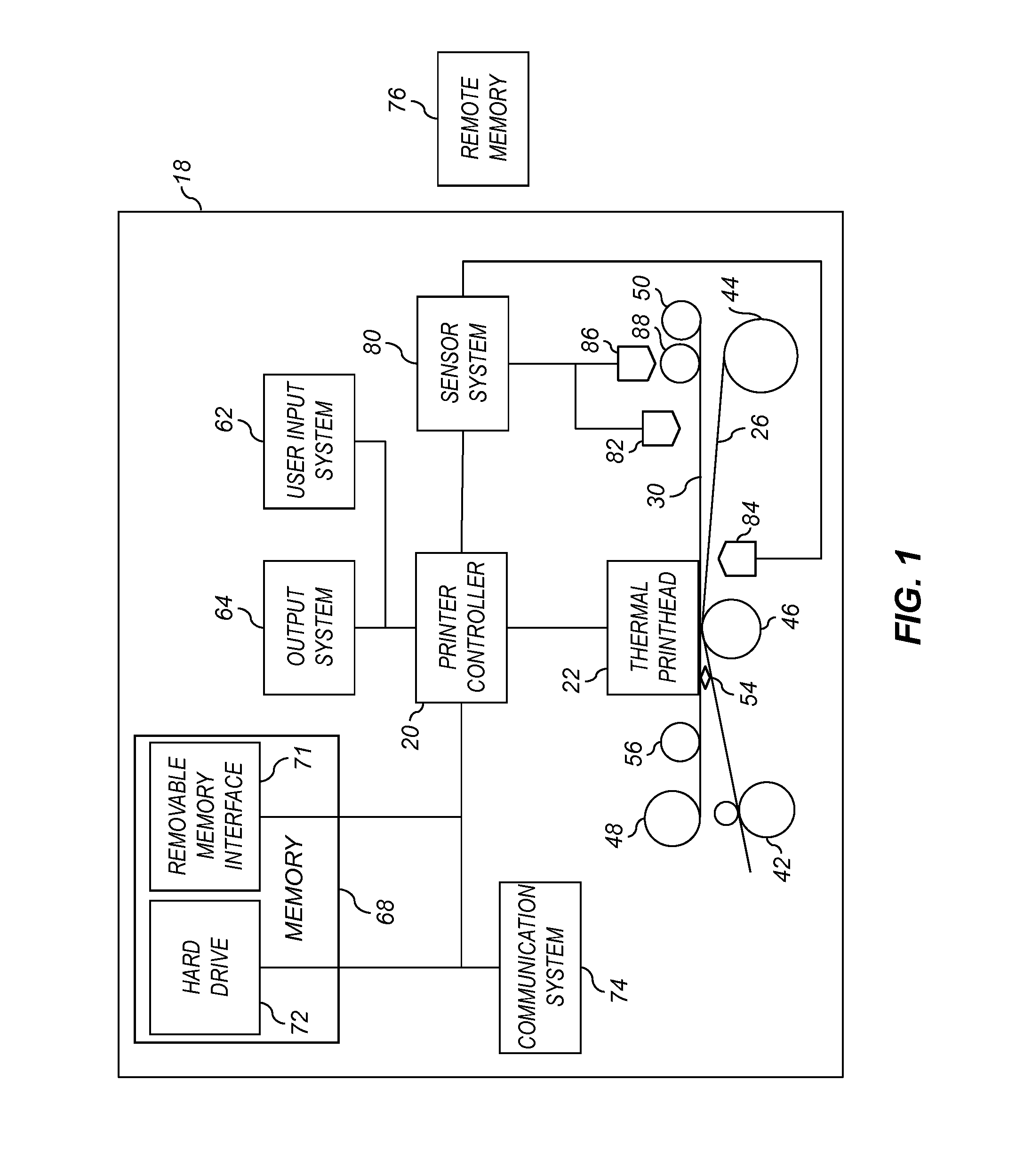
[0046]FIG. 1 shows a system diagram for an exemplary thermal printer 18 in accordance with the present invention. As shown in FIG. 1, thermal printer 18 has a printer controller 20 that causes a thermal printhead 22 to record images onto receiver media 26...


PUM


Abstract

A roll-fed duplex thermal printing system, comprising a supply roll of receiver media, a printing path, a reversing path, a diverter and a cutter positioned between the supply roll and the reversing path. When the diverter is in a first position the receiver media is directed from the supply roll or the reversing path into the printing path. When the diverter is in a second position the receiver media is directed from the supply roll into the reversing path. During a printing operation, the diverter is positioned in the first position and the receiver media is fed into the printing path where a first side image is printed. The diverter is then repositioned the receiver media is fed into the reversing path where it is cut. The diverter is then repositioned again and the receiver media is fed into the printing path where a second side image is printed.

Description

CROSS-REFERENCE TO RELATED APPLICATIONS[0001]Reference is made to commonly assigned, co-pending U.S. patent application Ser. No. 13 / 532,875, entitled: “Roll-fed duplex thermal printer”, by Mindler et al., which is incorporated herein by reference.FIELD OF THE INVENTION[0002]This invention pertains to the field of thermal printing systems, and more particularly to a roll-fed thermal printing system that provides duplex images.BACKGROUND OF THE INVENTION[0003]In thermal dye sublimation printing, it is generally well known to render images by heating and pressing one or more donor materials such as a colorant (e.g., a dye) or other coating against a receiver medium having a colorant receiving layer. The heat is generally supplied by a thermal printhead having an array of heating elements. The donor materials are typically provided in sized donor patches on a movable web known as a donor ribbon. The donor patches are organized on the ribbon into donor sets; each set containing all of th...

Claims


Application Information

Patent Timeline
IPC IPC(8): B41J3/60
CPCB41J3/60B41J13/0045B41J11/663B41J15/04B41J13/009
Inventor MINDLER, ROBERT F.HORVATH, ALEX D.TOMANOVICH, STEVEN J.
Owner KODAK ALARIS INC
Why Eureka
Try Eureka