Image read device and copier

a technology of image read and copier, which is applied in the direction of thin material processing, instruments, electrographic process equipment, etc., can solve the problems of image deterioration, read image signals, image deterioration

Inactive Publication Date: 2013-12-03
RICOH KK
View PDF23 Cites 801 Cited by
  • Summary
  • Abstract
  • Description
  • Claims
  • Application Information

AI Technical Summary

Problems solved by technology

In this type of image read device, because the original passes in contact with the transparent member when the images of the original are read, it is inevitable that dust, or the like, sticking to the image-surface side of the original adheres to the transparent member.
Furthermore, if an adhering material such as dust adheres to the read position of the transparent member, its effect appears on read image signals and the images are deteriorated.
The material adhering to the transparent member causes image deterioration in an image read device of not only the sheet-through type but also other types.
However, the effect appears on images as only a “point” in a type of image read device in which an original is fixed and an image read unit is moved in the sub-scanning direction to read the images, while it results in what is called a longitudinal line that extends in the sub-scanning direction and significant image deterioration is caused in a sheet-through type image read device.
However, in the above-described original read device, when an event causing the interruption of original conveyance occurs, the original being conveyed is stopped in an original conveying path.
As a result, there is a possibility that the original will be damaged if the original is stopped in the state described below.
As a result, the jammed part of the original MS is torn and the original is damaged.
As a result, the jammed part of the original is torn and the original is damaged.

Method used


Image

  • Image read device and copier
  • Image read device and copier
  • Image read device and copier

Examples


Embodiment Construction

[0034]An explanation will be given of an embodiment in which the present invention is applied to an electrophotographic-system copier (hereinafter, simply referred to as a copier) below.

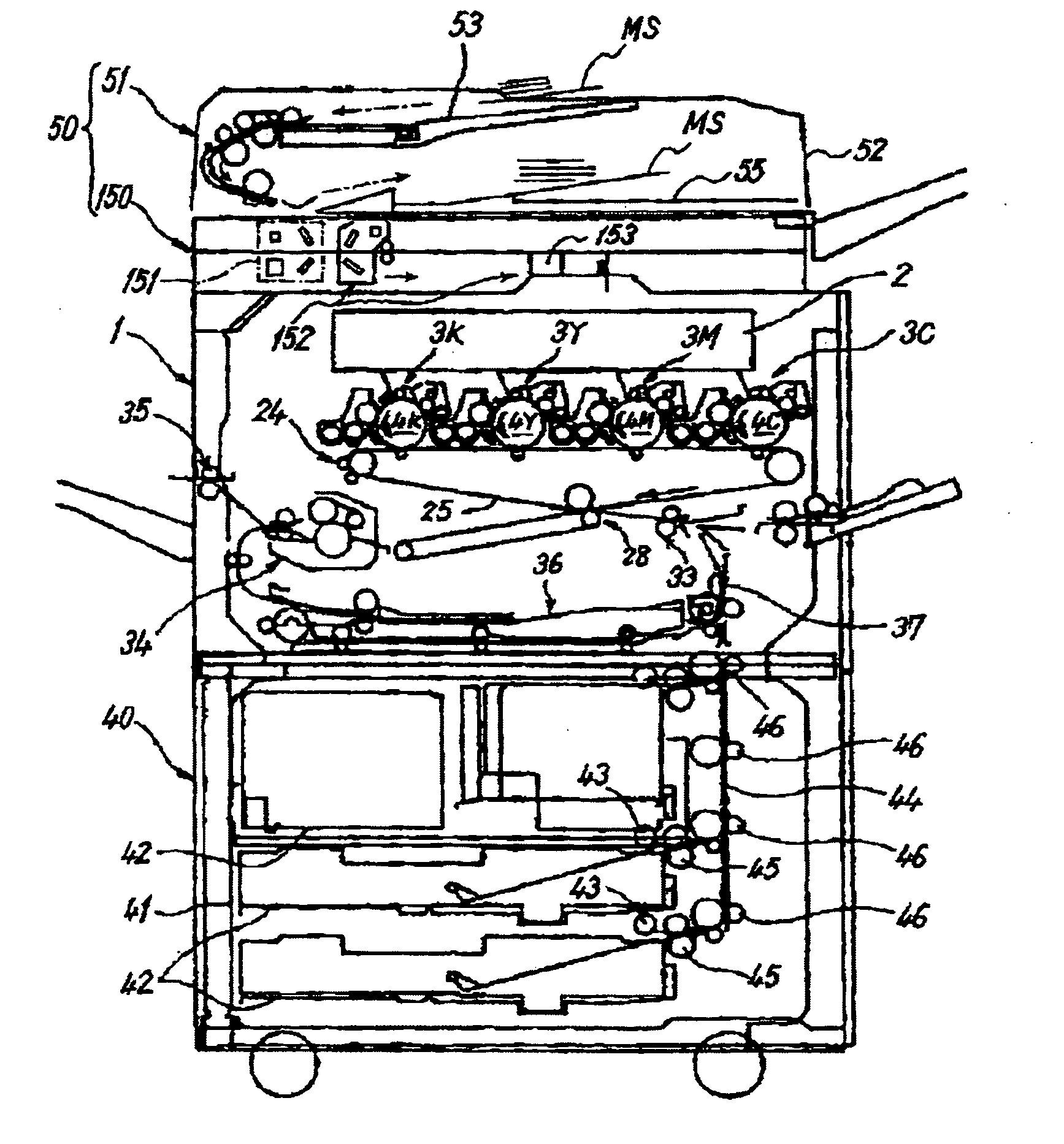
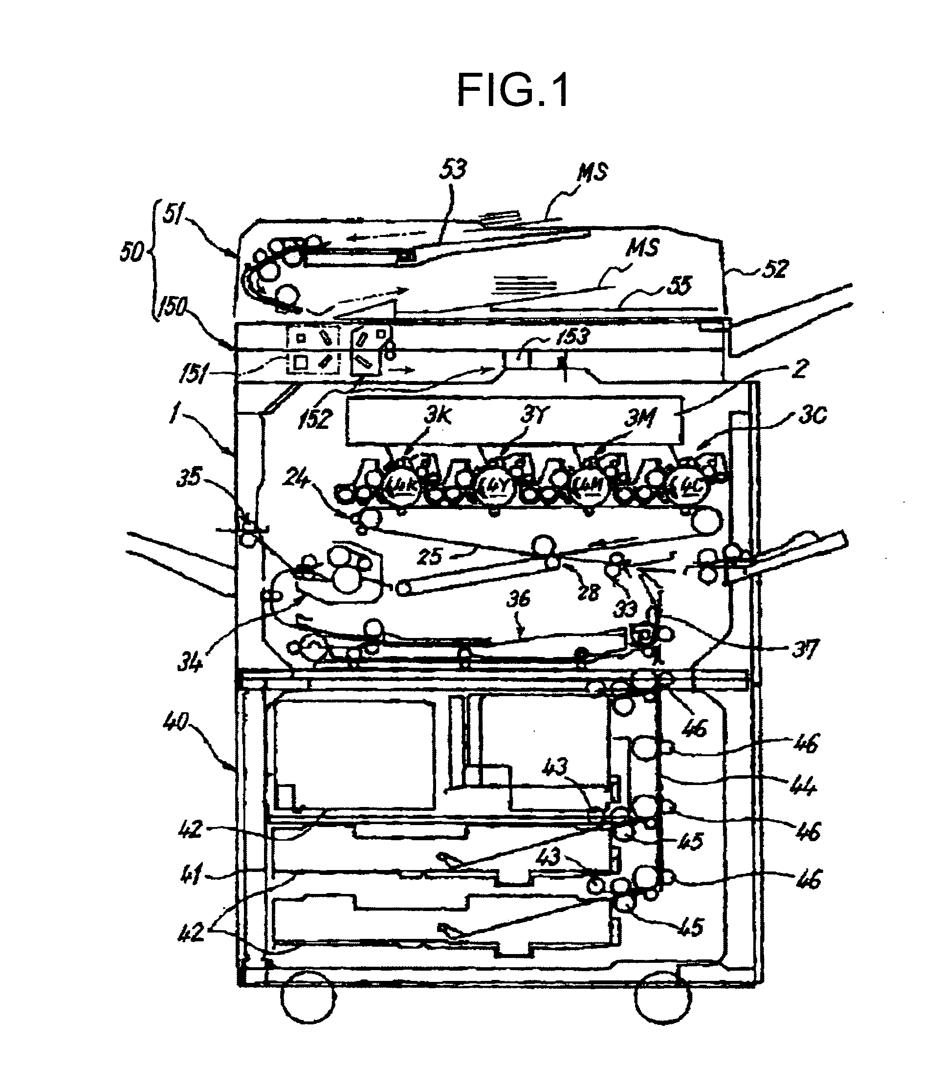
[0035]First, an explanation will be given of the basic configuration of a copier according to the present embodiment. FIG. 1 is an explanatory diagram that illustrates the schematic configuration of the copier according to the embodiment. The copier includes an image forming unit 1 that is an image forming means, a blank-sheet feed device 40, and an original read device 50. The original read device 50 includes the scanner 150 that is an original read unit fixed on the image forming unit 1 and the ADF 51 that is an original conveying unit supported by this.

[0036]The blank-sheet feed device 40 includes two feed cassettes 42 arranged at multiple stages in a paper bank 41, sending rollers 43 that send a transfer sheet from the feed cassettes 42, separation rollers 45 that separate the sent transfer sheet...


PUM


Abstract

An image read device is provided, which conveys an original while performing reading of an image of the original at a read position on a transparent member by a read unit fixed, the image read device including: a moving unit that moves the transparent member back and forth in an original conveying direction; a control unit that conveys the original and moves the transparent member by using the moving unit while causing the reading of the image to be performed at the read position; and a determining unit that, when an event causing interruption of original conveyance occurs, stops the transparent member and determines whether a control of returning the transparent member to a home position is to be performed or not in accordance with a stopped position of the original in an original conveying path.

Description

TECHNICAL FIELD[0001]The present invention relates to a sheet-through type image read device and a copier.BACKGROUND ART[0002]Heretofore, an image read device that is called a sheet-through type is known which conveys an original in a sub-scanning direction and passes the conveyed original through a fixed read position, thereby performing sub-scanning on images of the original. A transparent member is arranged at the read position of an image read unit in order to pass light emitted by a light source inside the image read unit toward the original on the outside or light reflected by an image surface of the original and projected toward the inside of the image read unit. In this type of image read device, because the original passes in contact with the transparent member when the images of the original are read, it is inevitable that dust, or the like, sticking to the image-surface side of the original adheres to the transparent member. Furthermore, if an adhering material such as du...

Claims


Application Information

Patent Timeline
Patent Type & Authority Patents(United States)
IPC IPC(8): H04N1/04
CPCG03G15/60H04N1/00689H04N1/00694H04N1/00705H04N1/0071H04N1/00713H04N1/00732H04N1/00734H04N1/00745H04N1/0075H04N1/00782H04N1/121H04N1/123H04N1/1235H04N1/1245G03G2215/00189H04N1/193H04N2201/0081
Inventor KUBO, HIROSHIFUJII, TAKASHIKOSUGA, YASUONAGANO, TATSUAKIMORITA, KENICHIROAKAI, TAKESHI
Owner RICOH KK
Why Eureka
Try Eureka